


Info from this week's video meeting.
20250821 ROS Lawn Tractor Automation meeting - Length 43:02 This video: https://youtu.be/4bg-js-SvdI
Go to the HTML index to get the description for this meeting:
http://sampson-jeff.com/RosAgriculture/LawnTractorMeetingNotes.htm#20250821

Finally got NoMachine working on the Rpi5 as the server and as a client on my laptop. I can control the Rpi5 from my laptop. Trying NoMachine on my iPad is nothing but trouble at this point. I’ll need more time to figure out what is going on. Duh I keep forgetting I can only use one client (iPad or Laptop) at a time. So now I’m good with NoMachine.
I got caught up on Slack backups. If you go here: http://sampson-jeff.com/RosAgriculture/slack_exports/ I currently have 5 blocks of backups. If you go into one of those backup directories you can open any HTML file. It will give you a close representation of the original Slack channel.
Info from this week's video meeting.
20250828 ROS Lawn Tractor Automation meeting - Length 1:07:58 This video: https://youtu.be/m1_X_gGtfbM
Go to the HTML index to get the description for this meeting: http://sampson-jeff.com/RosAgriculture/LawnTractorMeetingNotes.htm#20250828
======

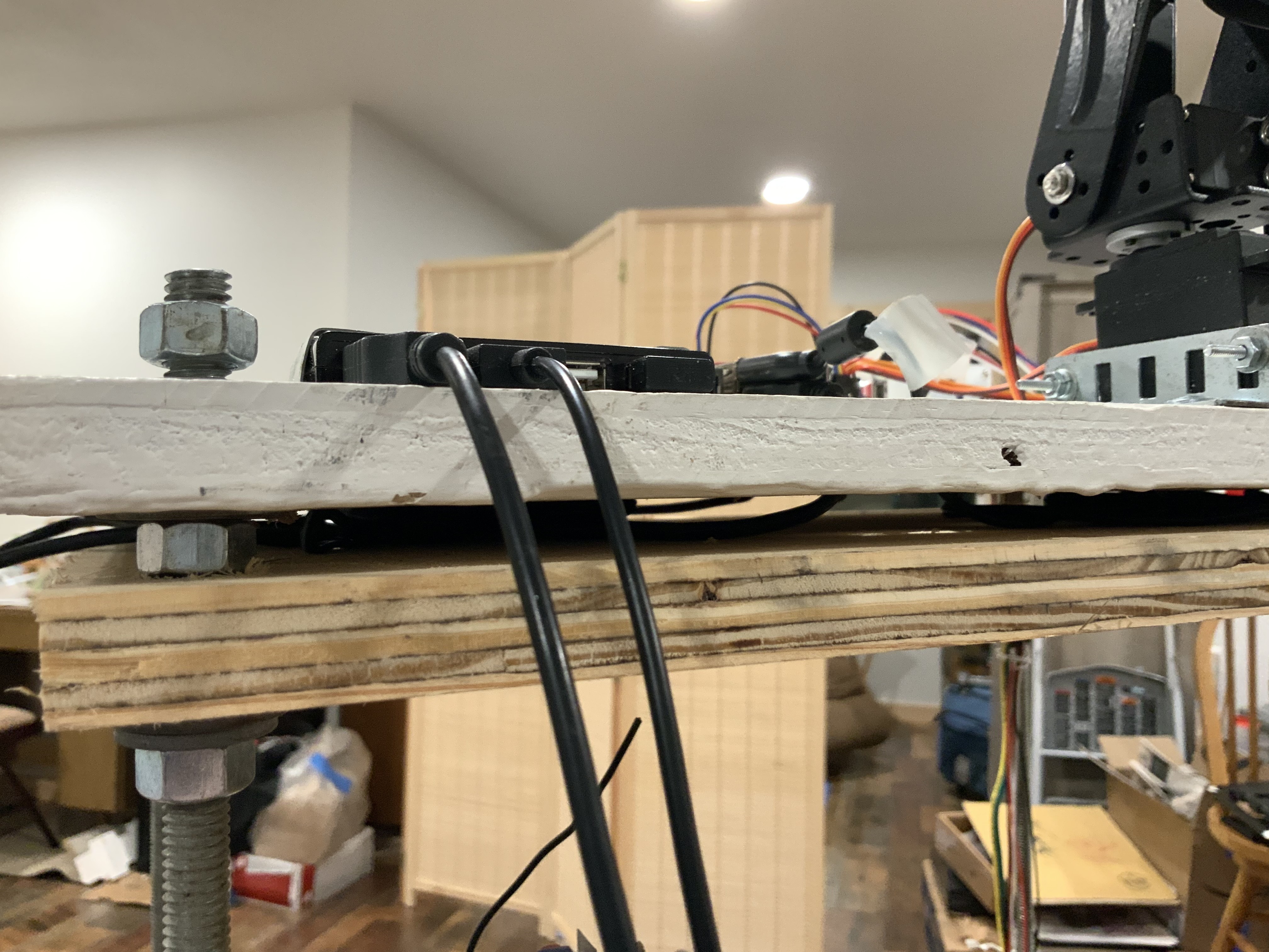
One step forward, 2 steps backwards,argh! Finally got the inside robot wired up on batteries. So I decided to do a cold start from the iPad and blue tooth keyboard. I turned on all the power switches, then using only NoMachine on the iPad with the blue tooth keyboard, I was able to activate and remote control the bot. No attached usb peripherals or monitor. BUT THEN I decided to make some minors changes remotely, ie adding comments and adjusting servo angles with just the iPad and BT keyboard. Long story short I hosed things up. The iPad screen is too small to keep track of every thing. The iPad is ok to see the camera and operate 2 servos at a time. I’ll have to plug in the usb and monitor to correct and make future changes.
During our last video meeting I suggested that you may be able to plug your monitor into either HDMI connector on an RPi5 (and probably an RPi4) and it will work either way. Since Bob has clearance issues between his HDMI adapter and his USB-C power connector. I tried the second HDMI connector on my RPi4 tonight and it came up and worked just fine. I opened Settings|Displays (on Ubuntu) and it didn't even bother to mention I was on the second display. Something like dmesg might make mention of the irregularity...
This is an iPhone video recording, watching the playback of a video taken by a camera on my robot. The camera on a robot is stationary. Movement that your witnessing is a result of me turning the robot left and right with drive motors. I’m controlling the robot through NoMachine software on the robot and the iPad. In order to avoid fat finger syndrome, causing problems on the iPad. I’m using the iPad pencil. I’m controlling the robot motors by way of the Bluetooth keyboard. movement is controlled by pressing individual keys on the keyboard. I have to figure out how to multitask multiple keyboard, keys, to drive the motors and servos for the camera at the same time.

*Thread Reply:* I don’t know how the no no message got in there, please disavow. I can’t seem to get rid of it.
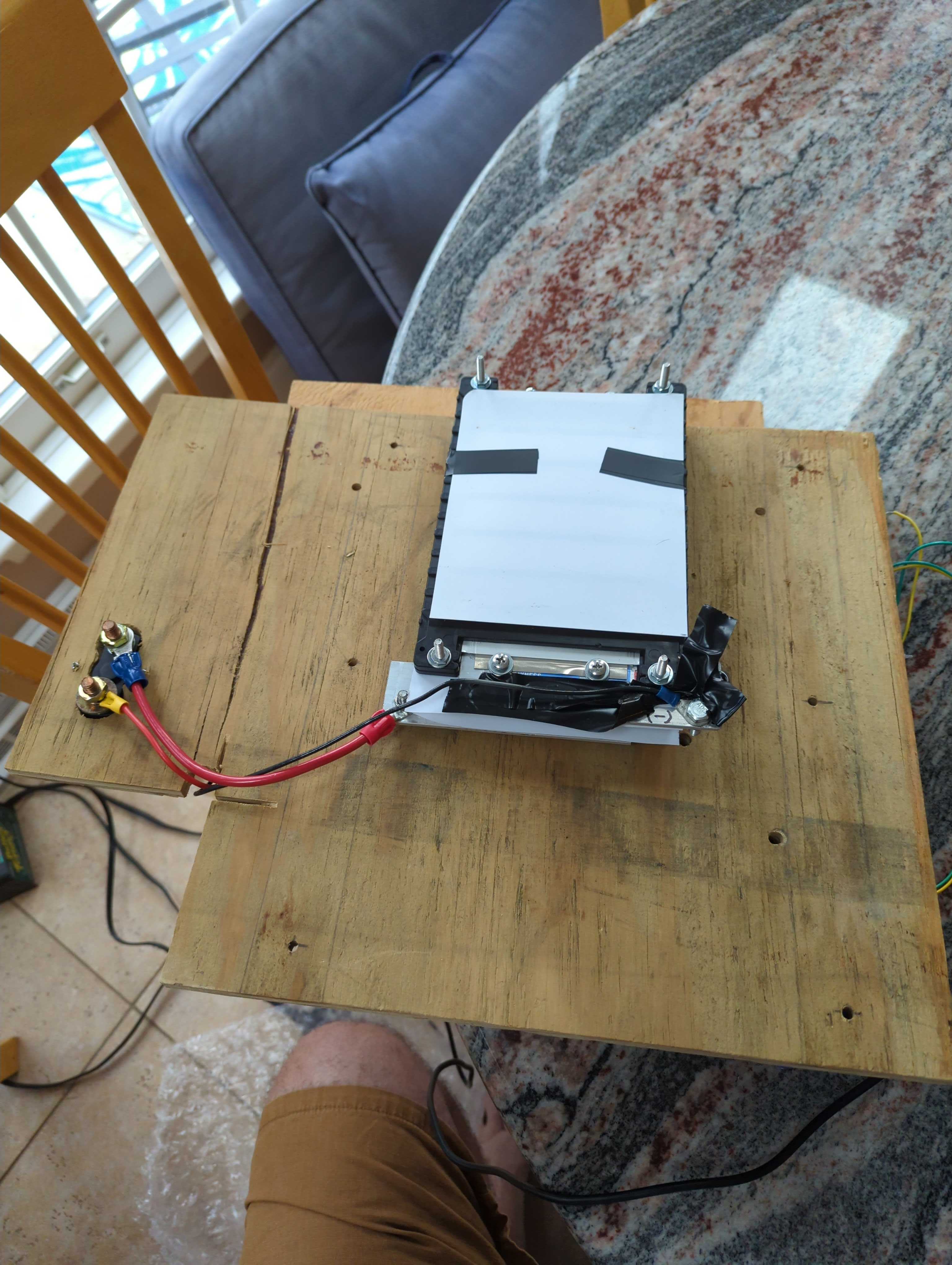
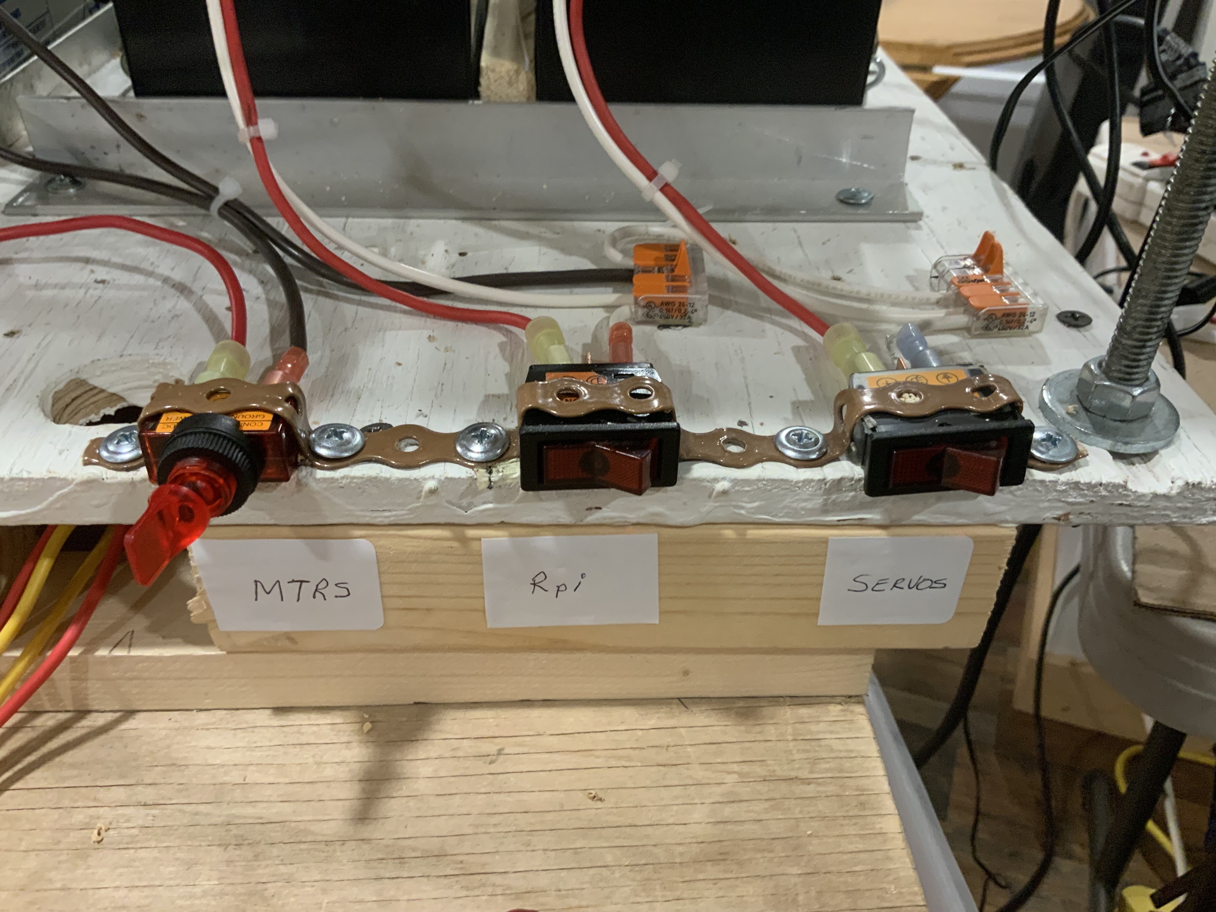
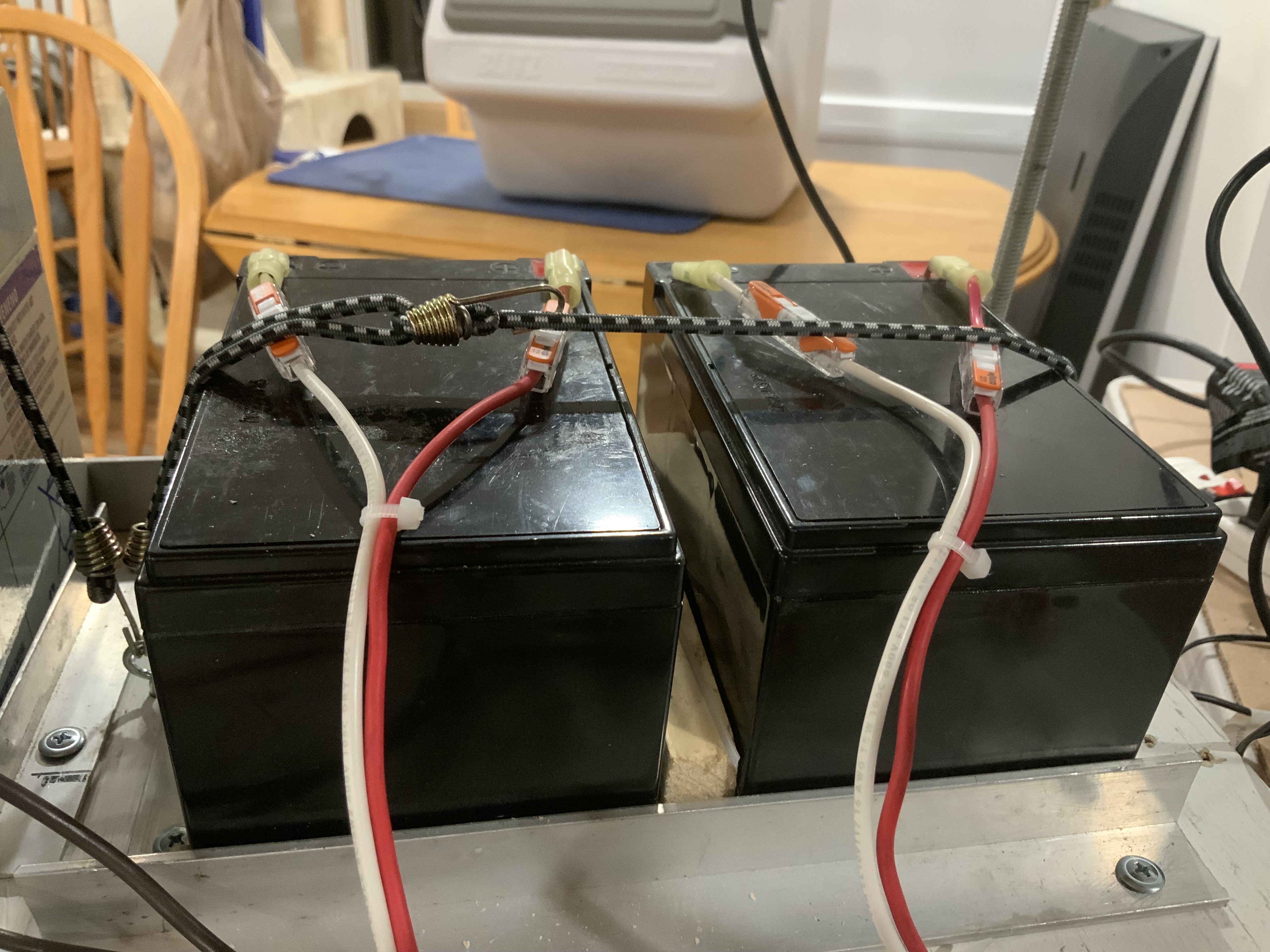
Will touch on current status of the few wiring changes. I removed the exposed battery posts.
Info from this week's video meeting.
20250904 ROS Lawn Tractor Automation meeting - Length 49:12 This video: https://youtu.be/FkXUdxvHhdw
Go to the HTML index to get the description for this meeting: http://sampson-jeff.com/RosAgriculture/LawnTractorMeetingNotes.htm#20250904
======

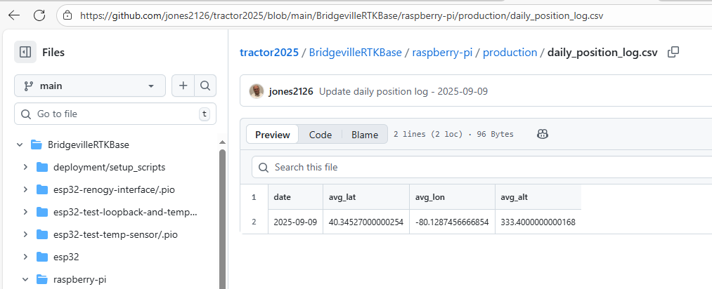
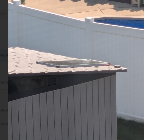
I have moved my RTK Base off the back porch and put it in a more permanent spot in and on top of our shed. I decided to log daily the 24 hour average of the location. I have a cron job that will post that to a GitHub .csv file every day at 10 am. It's not exactly needed, but it can be another way of ensuring the solar panel, battery and RPi are running smoothly.
Info from this week's video meeting.
20250911 ROS Lawn Tractor Automation meeting - Length 56:28 This video: https://youtu.be/oL72OKOL4Xc
Go to the HTML index to get the description for this meeting: http://sampson-jeff.com/RosAgriculture/LawnTractorMeetingNotes.htm#20250911
======

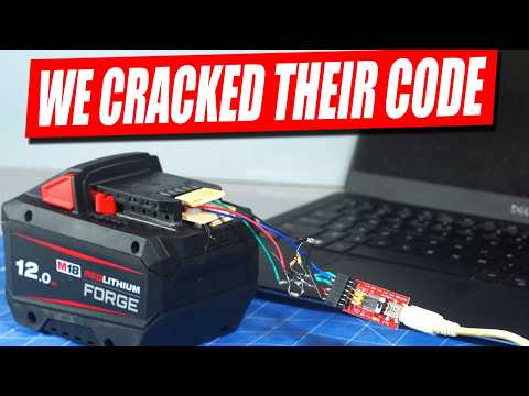
New video. People have reverse engineered the diagnostic codes on the batteries that @TERRY SCHUMACHER is playing with.
https://www.youtube.com/watch?v=tHj0-Gzvbeo
@JeffS had asked about the digits of precision of my RTK base station F9P. It seems the 'out of the box' default for the GGA NMEA sentence is 4 digits.
$GNGGA,190035.00,4020.71620,N,08007.72474,W,1,12,99.99,333.4,M,-34.2,M,,**4B
I changed it to 7.
$GNGGA,210653.00,4020.7161959,N,08007.7247435,W,1,12,99.99,333.370,M,-34.193,M,,**4F
For anybody that thinks this looks odd... (It is all hard to read on the video, but that is a different problem.) It looks like GPGGA displays as degrees and minutes. 4020.71620 http://lefebure.com/articles/nmea-gga/ Al's log files display as degrees (i.e., degrees and decimal degrees) 40.34527000034152 https://github.com/jones2126/tractor2025/blob/main/BridgevilleRTKBase/raspberry-pi/production/daily_position_log.csv And there is a third format (degrees,minutes,seconds)
So you have to be aware of which format is being used...
Here is a translator (and maybe some description): https://latlongdata.com/lat-long-converter/
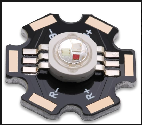
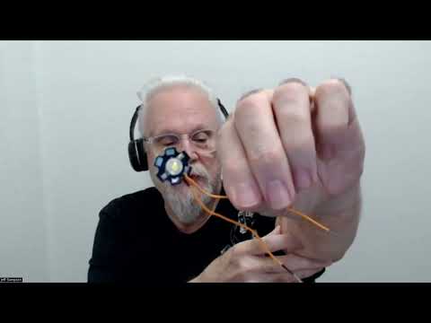
I am still trying to find good examples of how to test this 6 pad, 1 W LED that has a stencil for R+, R-, B+ and B-. I did find this. https://kitronik.co.uk/blogs/resources/how-to-use-1w-star-led and this https://www.youtube.com/watch?v=CUTX6YkbBsc but they don't seem to be microcontroller controlled or generating different colors.

Oh, I clicked "End meeting" instead of "Stop recording".
But it just occurred to me, since Al is using a Teensy (of some version), he probably has extra PWM channels available already. So he doesn't have to add the extra PWM board.
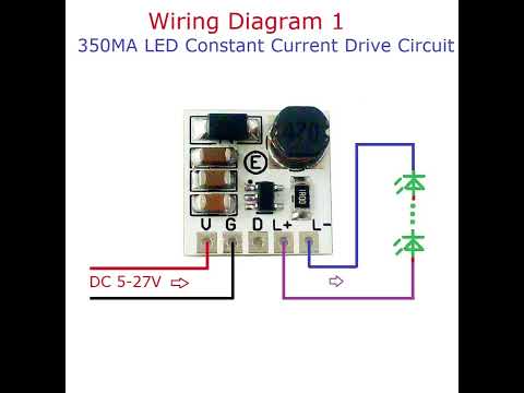
Also, these are the type of drivers I am using. https://www.amazon.com/High-Power-Trigger-Adjustment-Electronic-Brightness/dp/B0893MKNB2/ref=sr_1_2 (search for best deal)
Are you using a resistor for current limiting? Or just setting you power supply to 350ma?
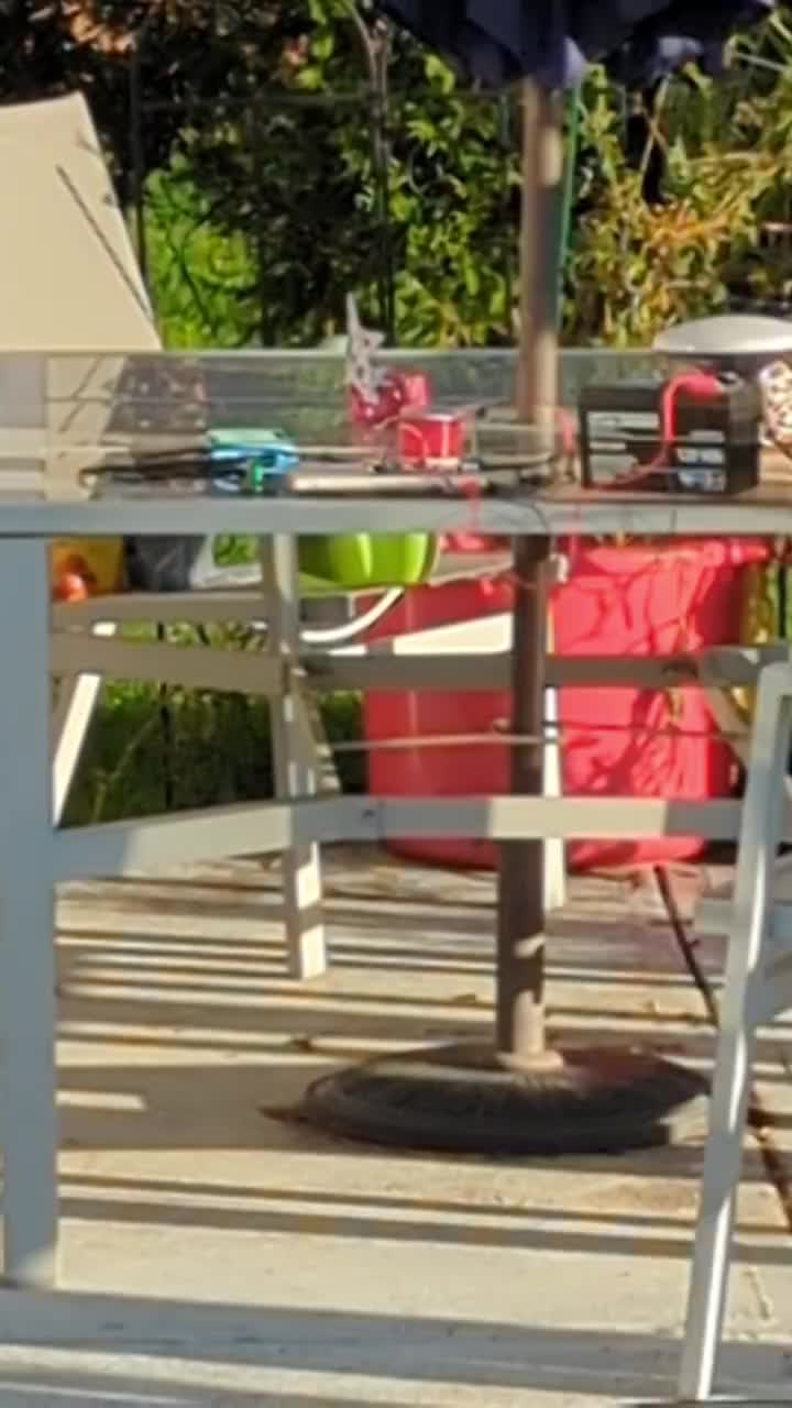
Since you have a setup that works, drag it out to your garage (or picnic table) and see what it look like in bright sunlight.
Also you could check the temp at 350ma. (be careful, you don't burn yourself).
(Back in the old days they referred to burning a company logo on your finger when foolishly checking temperature of devices.)
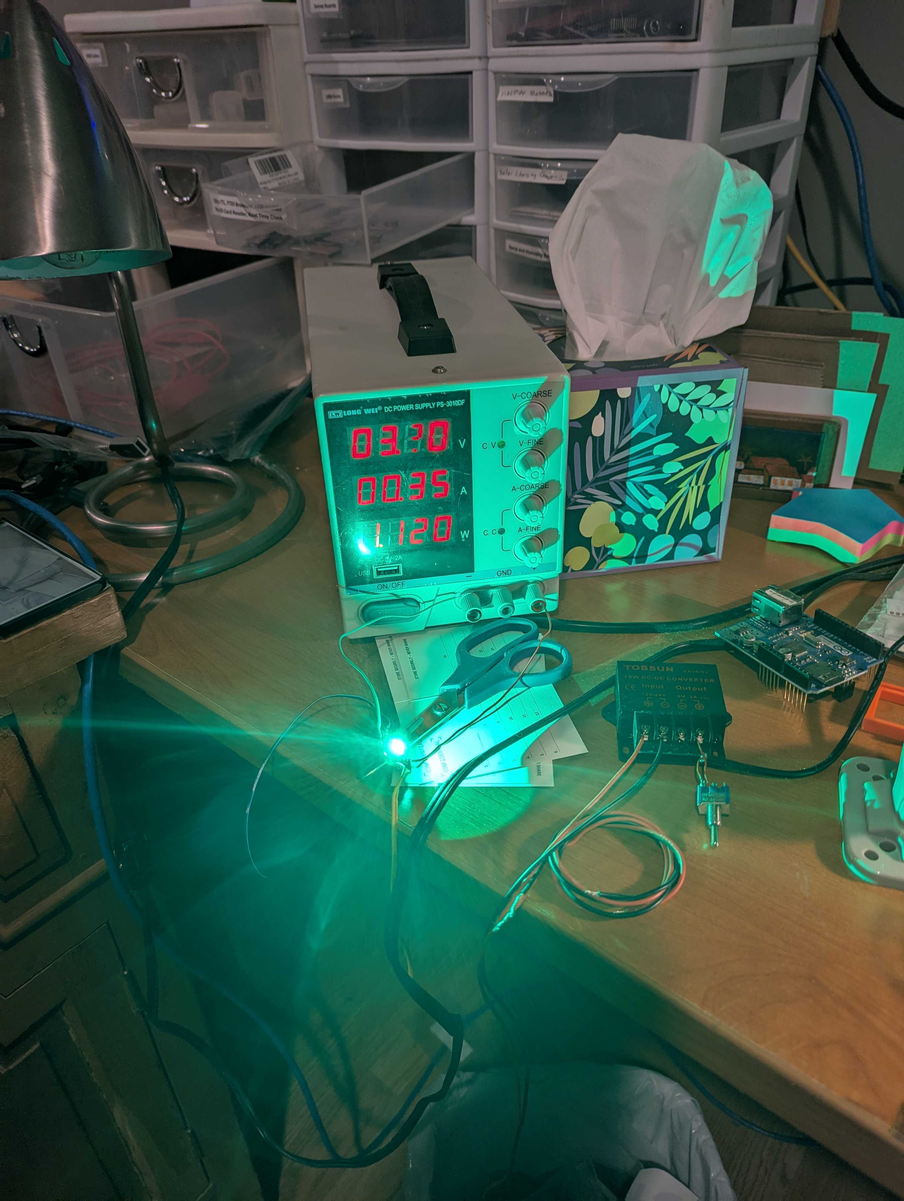
No resistor. Just hoping the power supply does what is says and limits the power to 3V @ .35 amps. Blinding...😎
i just ran across current source LED drivers. I have never looked at that before. After I get the video meeting published I will dig into that...
Info from this week's video meeting.
20250918 ROS Lawn Tractor Automation meeting - Length 42:11 This video: https://youtu.be/rb_Q1jCHEqI
Go to the HTML index to get the description for this meeting: http://sampson-jeff.com/RosAgriculture/LawnTractorMeetingNotes.htm#20250918
======

I see my of criticism of A-Holes does make it through the filters of the worthless A-Holes that are using (abusing?) our video meetings. This is their take on what I said about them...
Debunking the AI Myth In a lively debate that followed, Jeff took center stage to debunk the mythos surrounding artificial intelligence. Armed with facts and figures, he stressed the importance of being well-informed in a landscape rife with misinformation. His impassioned plea for rational discourse struck a chord with the audience, prompting introspection on the true essence of technological advancement.
It took them about one hour for their "analysis" of our video meeting was posted. You can see the rest of their dribble here: https://www.mowrs.com/20250918-ros-lawn-tractor-meeting/
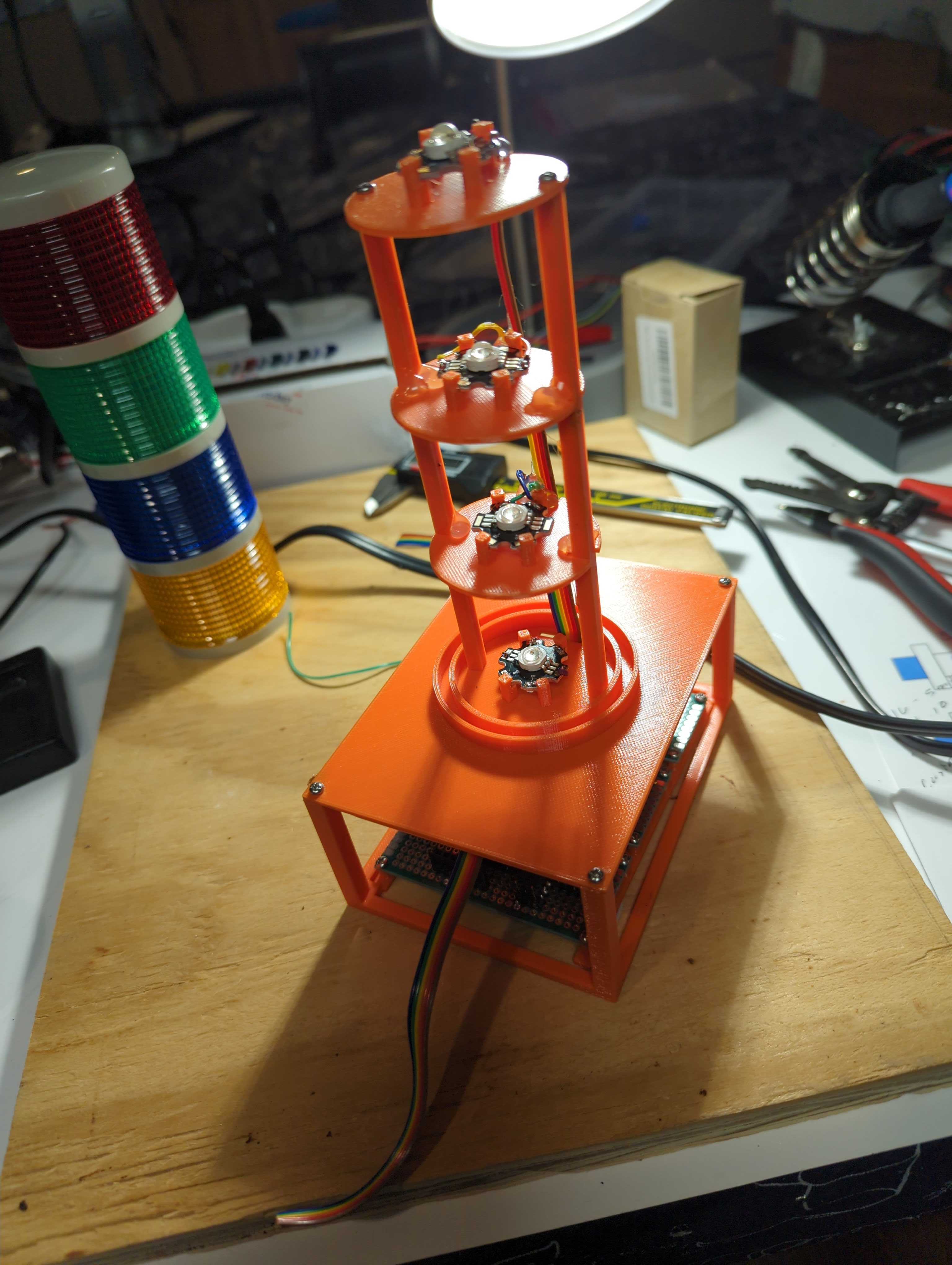
I was just reminded. If you go to this video @7:00 I am talking about the construction of my flashing beacons. https://www.youtube.com/watch?v=kZkRv-ihn9o
Or go to the index file and go to the date 07122019 you can see the rest of the index for that meeting. http://sampson-jeff.com/RosAgriculture/ros-agriculture-youtube20230104.txt

*Thread Reply:* Remind me again how to search the index file by keywords?
*Thread Reply:* Pull up either file: http://sampson-jeff.com/RosAgriculture/LawnTractorMeetingNotes.htm or http://sampson-jeff.com/RosAgriculture/ros-agriculture-youtube20230104.txt
Do a Ctrl-F and type in your keyword and let it search.
I see the original READ ME file went away... I'll see if I can track that down.
*Thread Reply:* Oh, the READ Me file was marked as a hidden file. Now it shows up if you look here: http://sampson-jeff.com/RosAgriculture/
*Thread Reply:* Code Ive been trying for servos and motors seems to be tanking and turning off Rpi. I suspect I’m getting brown outs because my battery isn’t big enough. So …..add another small 12v or go to auto sized battery. Maybe a marine type battery.
*Thread Reply:* Where are your servos getting power? Is it the it the same supply that is powering the RPi?
*Thread Reply:* Pi and servos off the same battery. I know better but I thought I could cheat for a little while! This thing is getting too big to carry up and down the stairs.
*Thread Reply:* It is not that they are on the same battery, it is that they are both coming from the same 12V-to-5V convertor. So if you have a separate 5V supply then you have a better chance of it working. I would have your current 5V convertor just driving the RPi. Then have a separate 5V supply for everything else.
*Thread Reply:* I’ll dig around and see if I can find another 12v battery I can carry. I’m still limited range of motion and lifting capability.
*Thread Reply:* @Al Jones @JeffS guess I’ll be shopping for new batteries for the electronics. What do ya recommend?
*Thread Reply:* @Bob Hassett Regarding a battery, I'm biased towards something like a 12V garden tractor, lead acid battery. They are readily available, have more amps than the 'Barbie Jeep' style battery, can withstand the cold and be charged with available chargers. The Barbie Jeep motors were designed to carry a child, so I think you have plenty of power to carry the weight of your setup.
Finally! Just using usb wireless keyboard. Only way I can lift the bot off the test stand is to disconnect a minimum of 1 battery. I gotta remember to turn off the microphone while recording!
I see a “replied to a thread” from @Al Jones “I was just reminded if you go to this video @7…” it was in blue indicating a link?
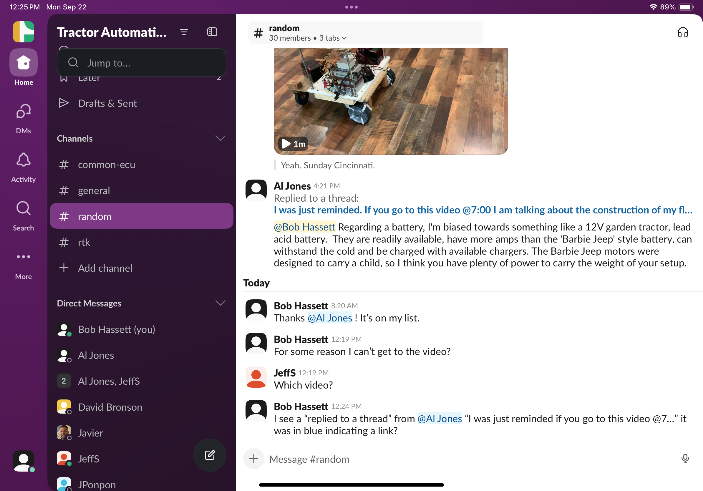

If I click on the link "I was just reminded,,," it opens the thread from September 9th at 9:02 PM. That thread has a link to the ROS Agriculture video.
I think there is extra confusion because people are using the extra Slack features which were deigned to confuse people.
HBRC is going through the RPi5 5 amp power supply problem... https://groups.google.com/g/hbrobotics/c/cbc14JKpISI
Info from this week's video meeting.
20250925 ROS Lawn Tractor Automation meeting - Length 1:21:01 This video: https://youtu.be/CMZL90kASlo
Go to the HTML index to get the description for this meeting: http://sampson-jeff.com/RosAgriculture/LawnTractorMeetingNotes.htm#20250925
======
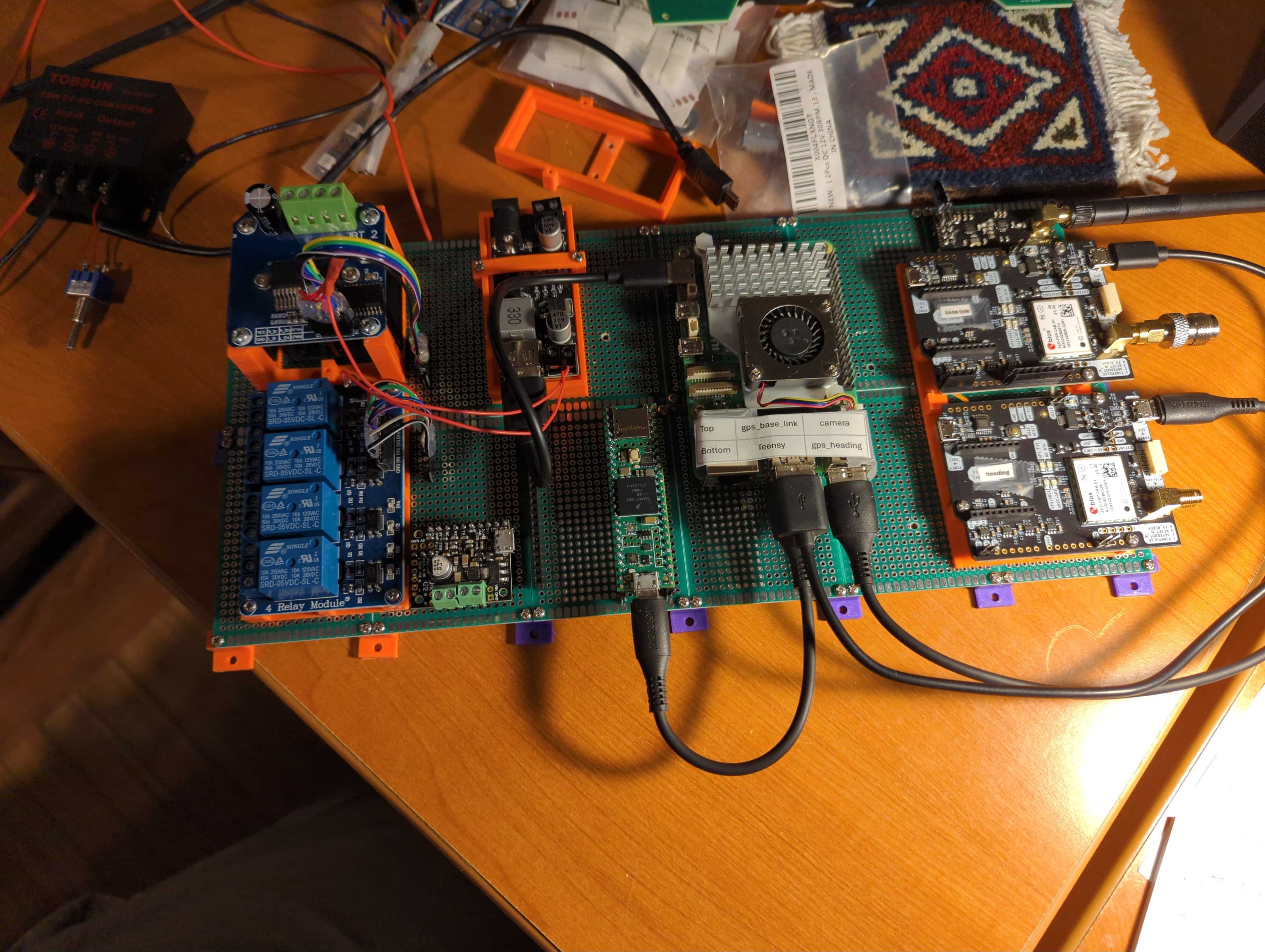
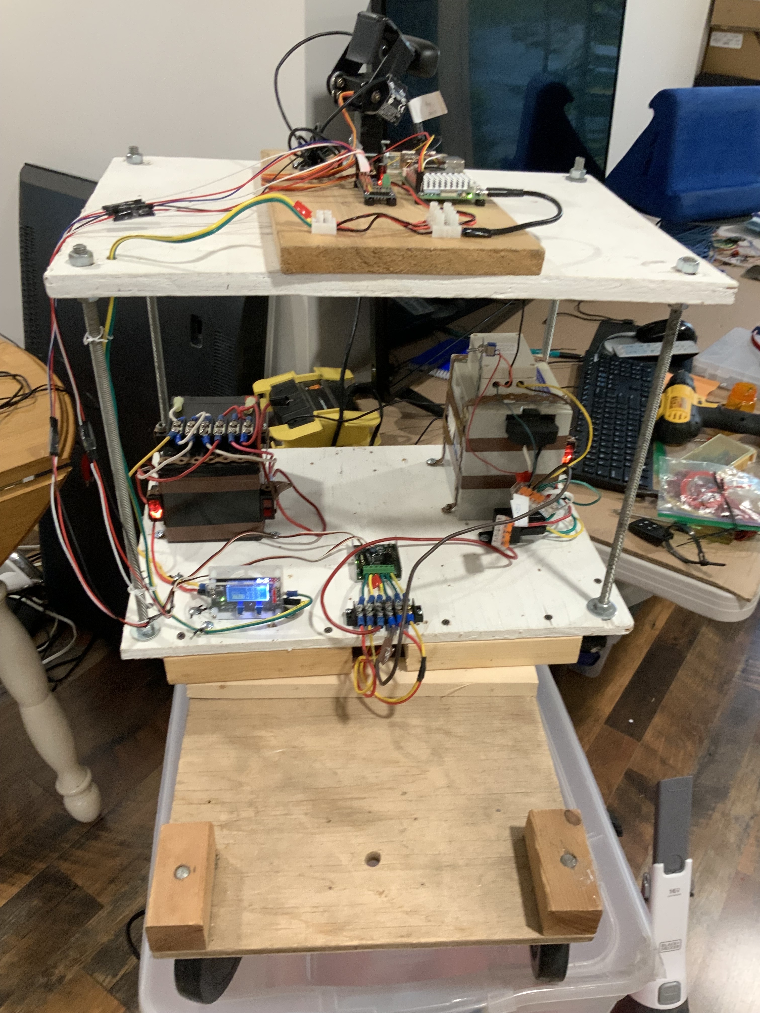
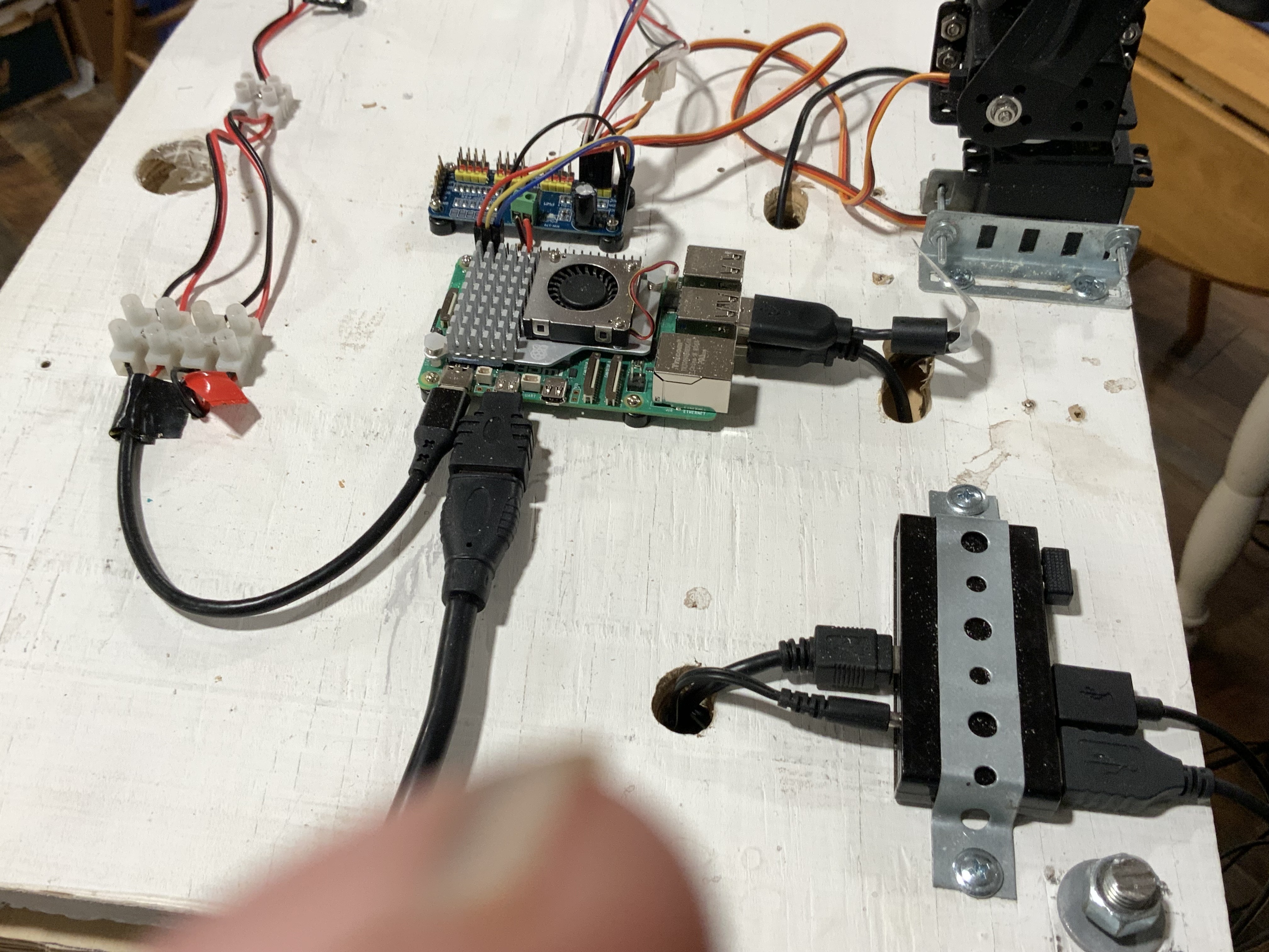
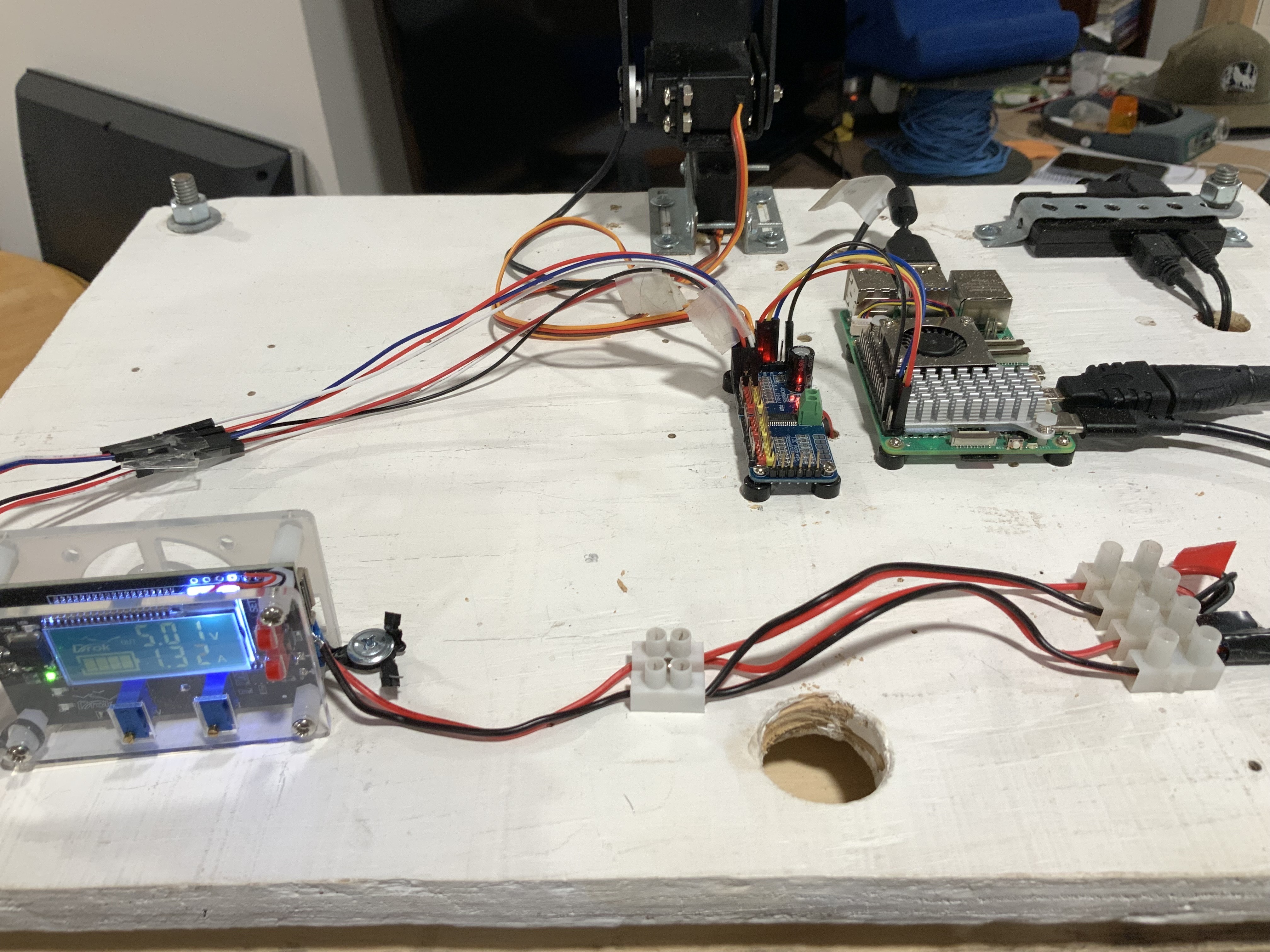
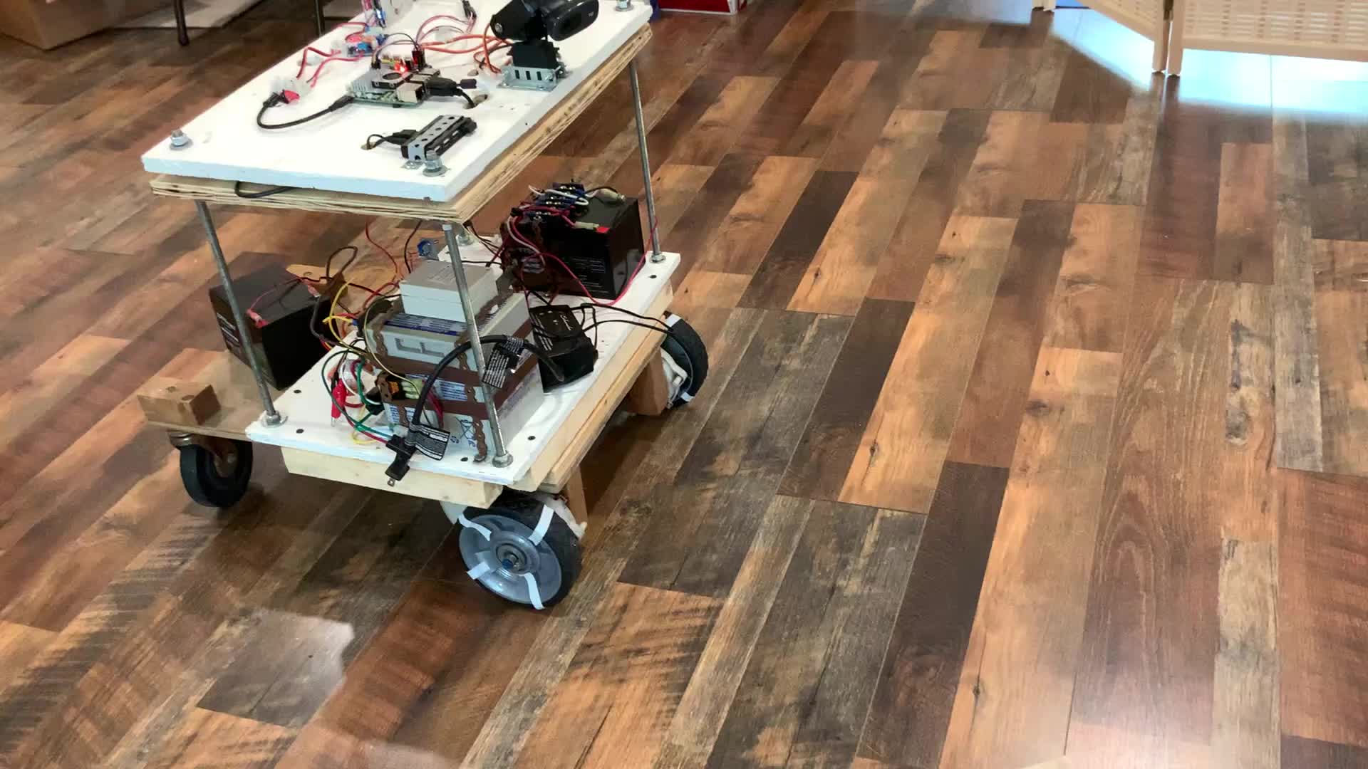
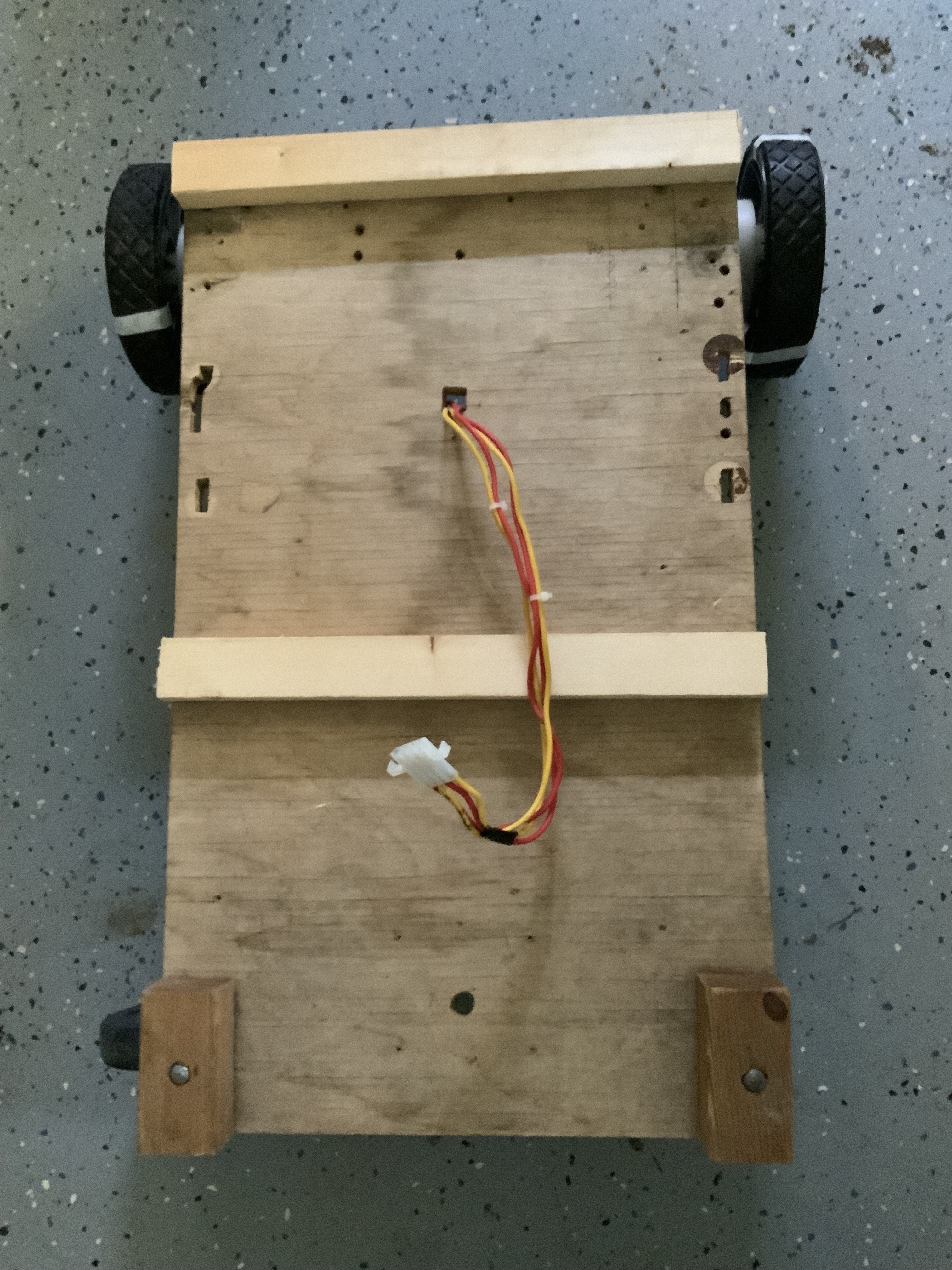
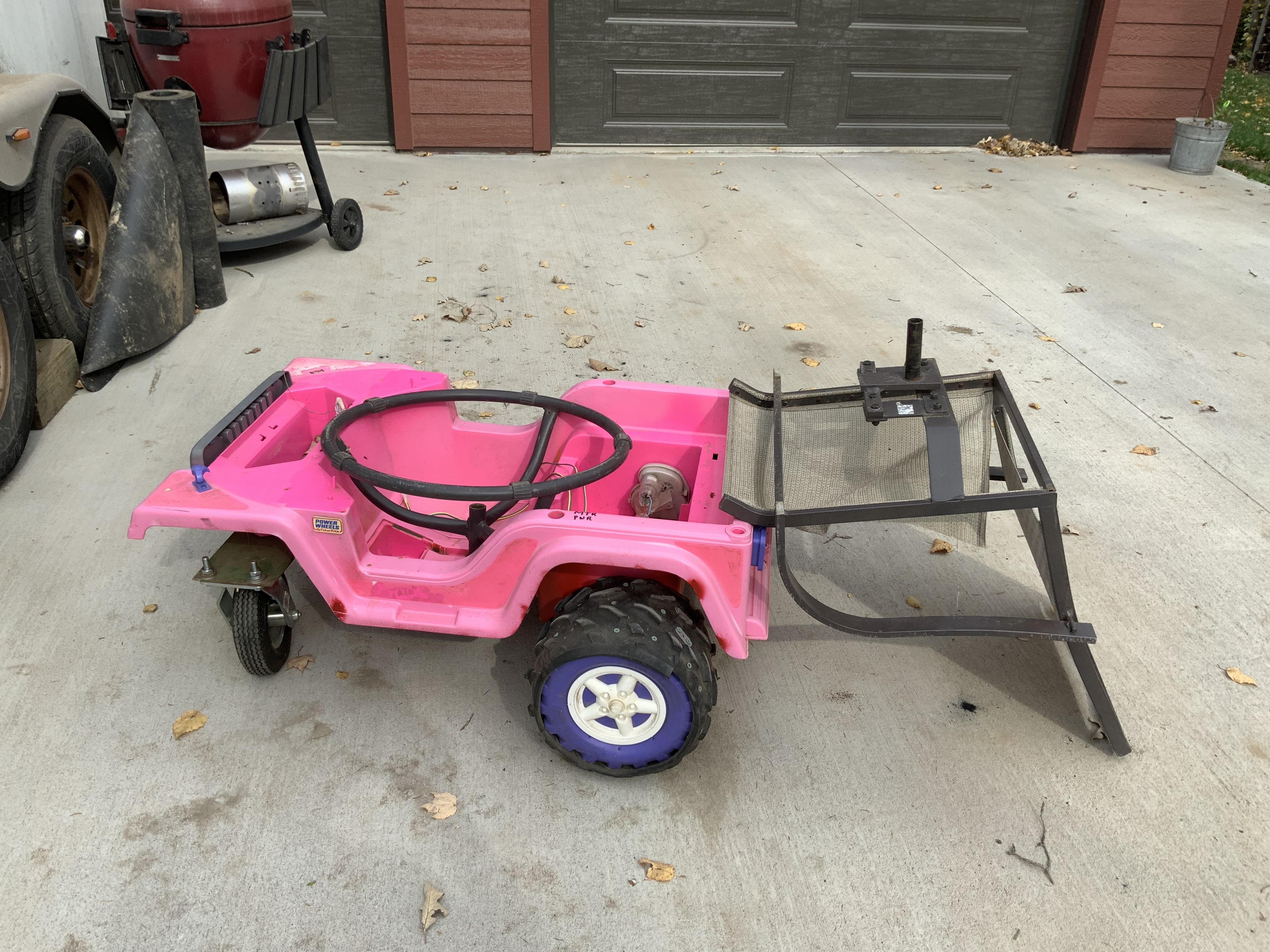
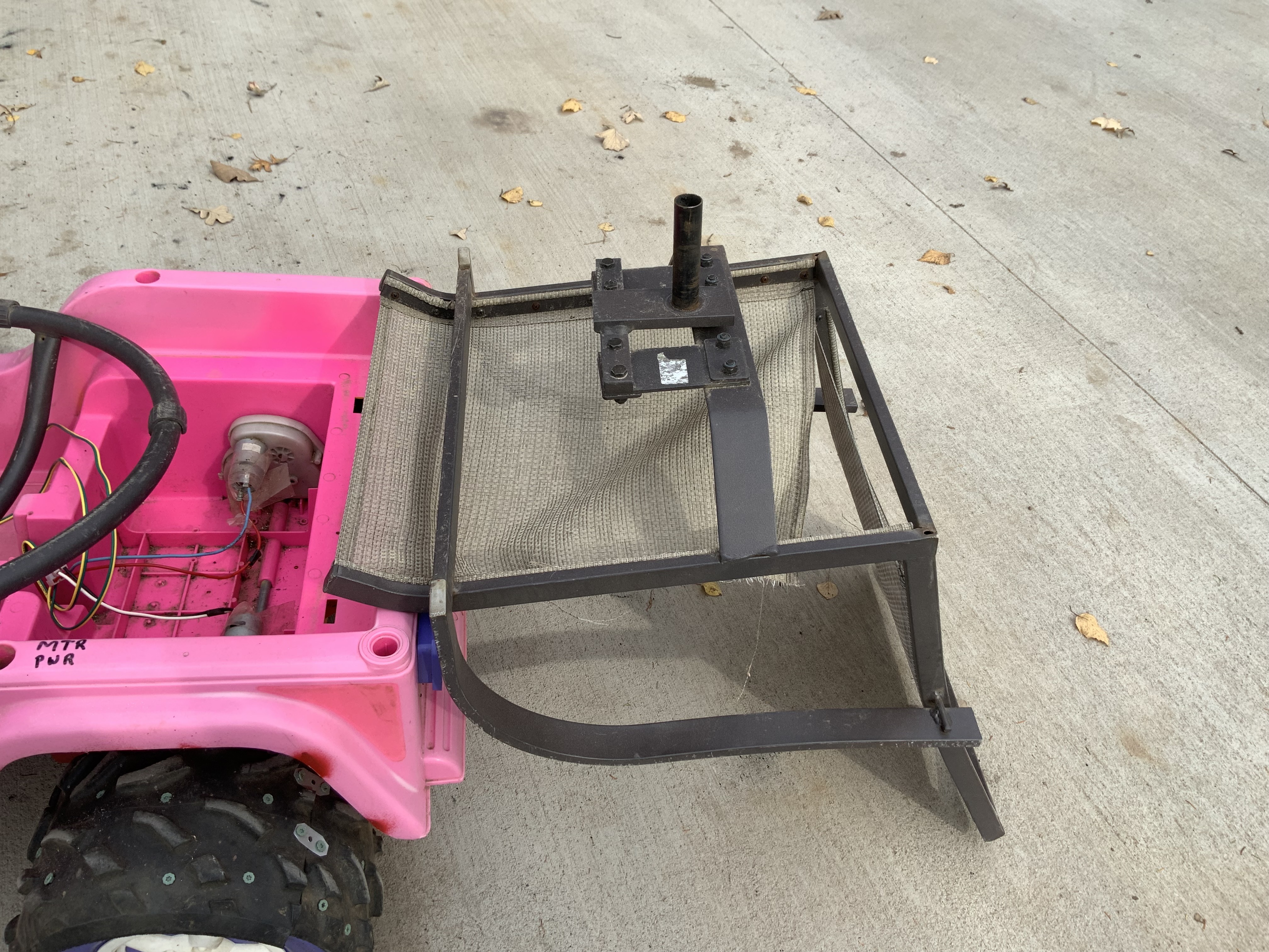
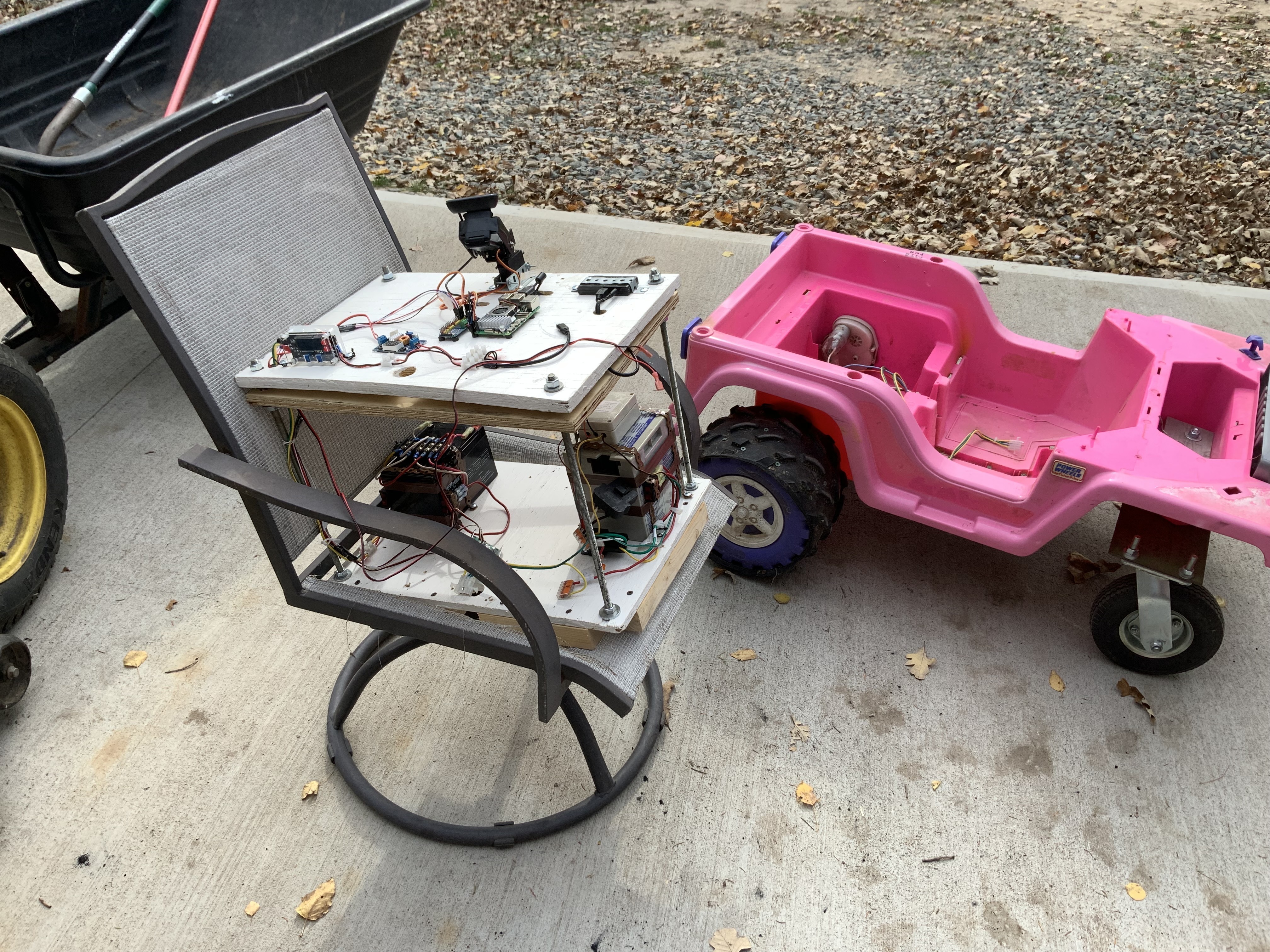
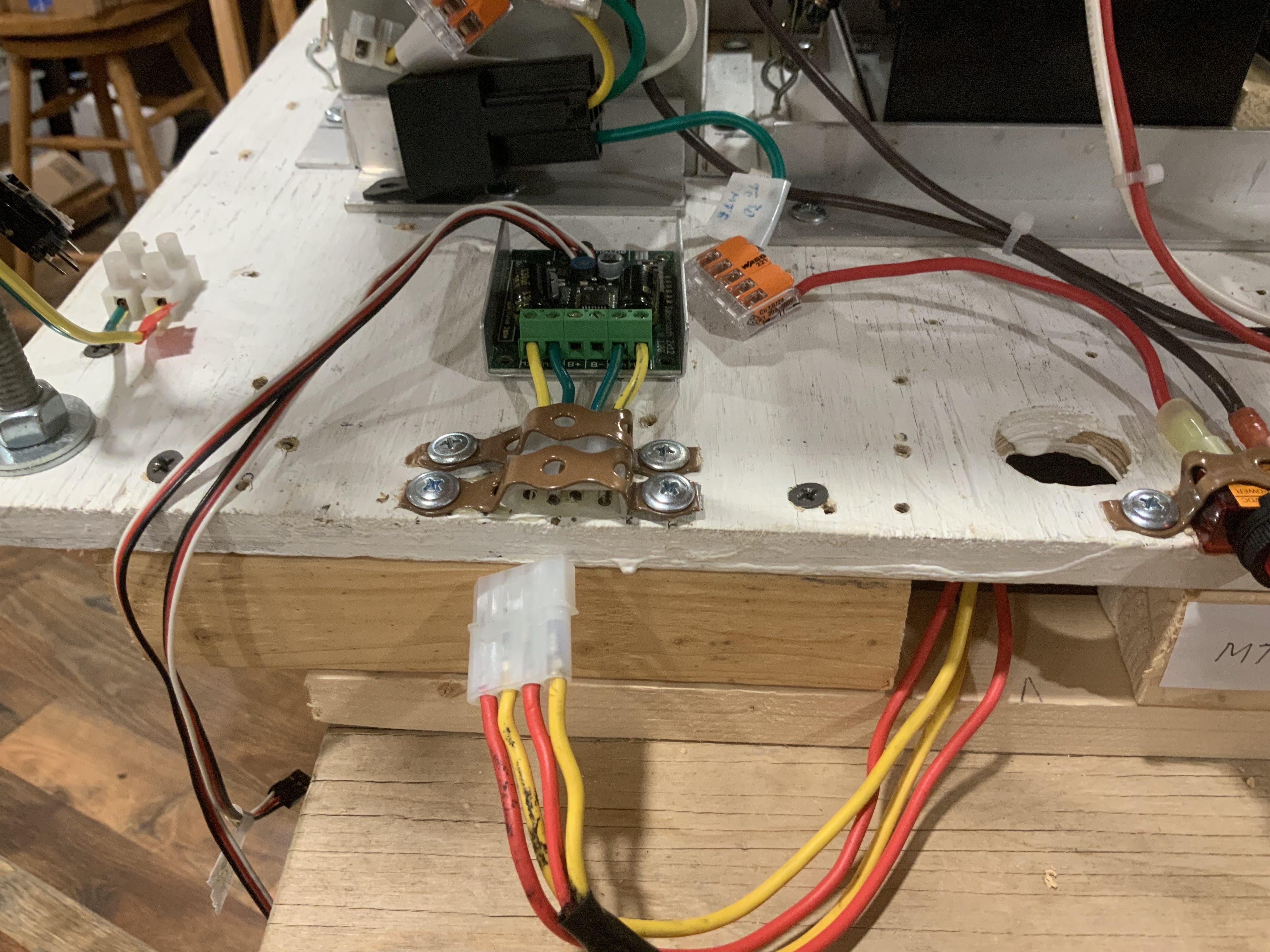
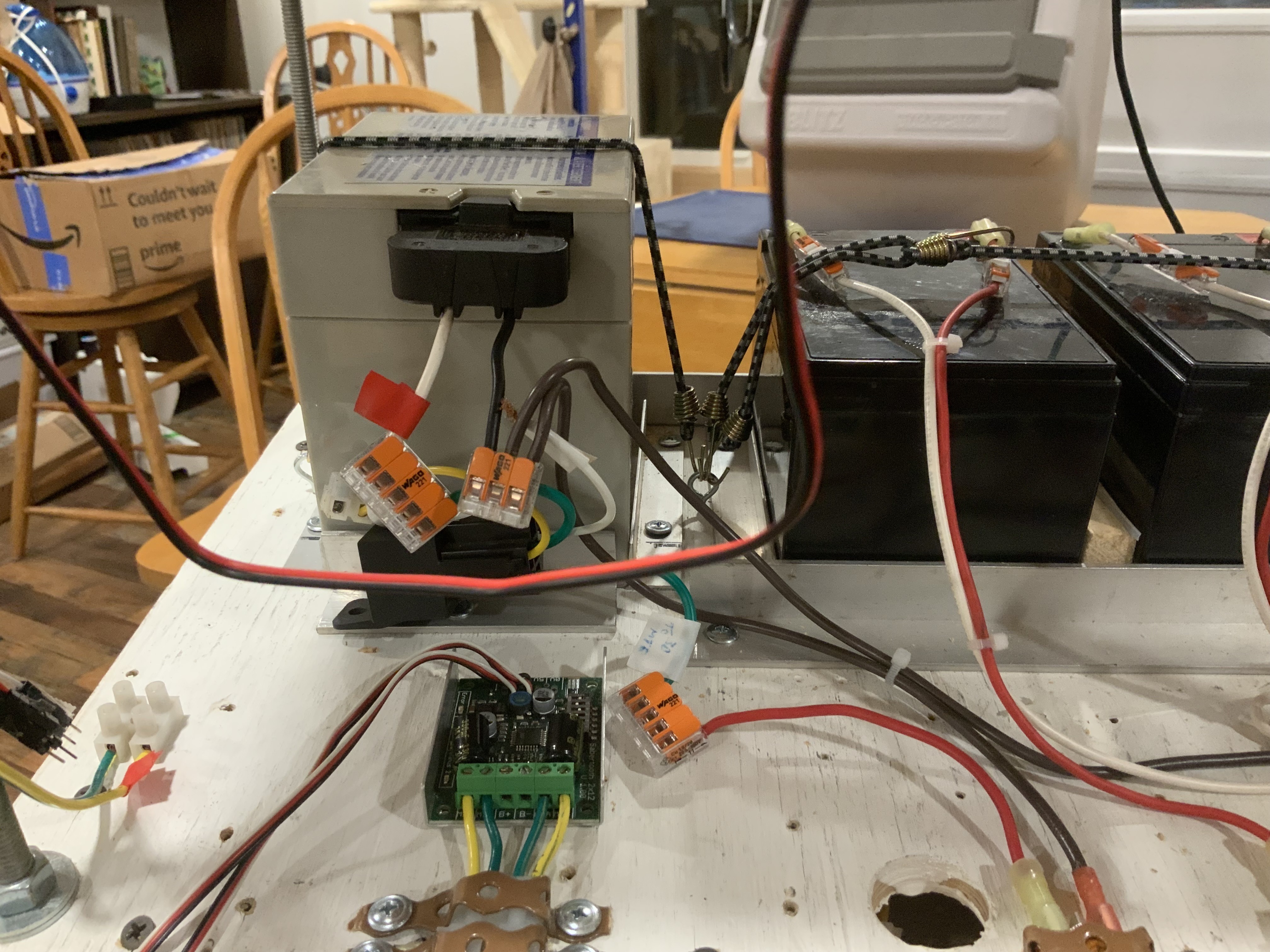
The picture on the right is my indoor “Mini” motor setup
. I didn’t know how to refer to the double deck electronic decks. @Al suggested calling it “Beast”.
Sooo.
I’ll call it “Da Beast”.
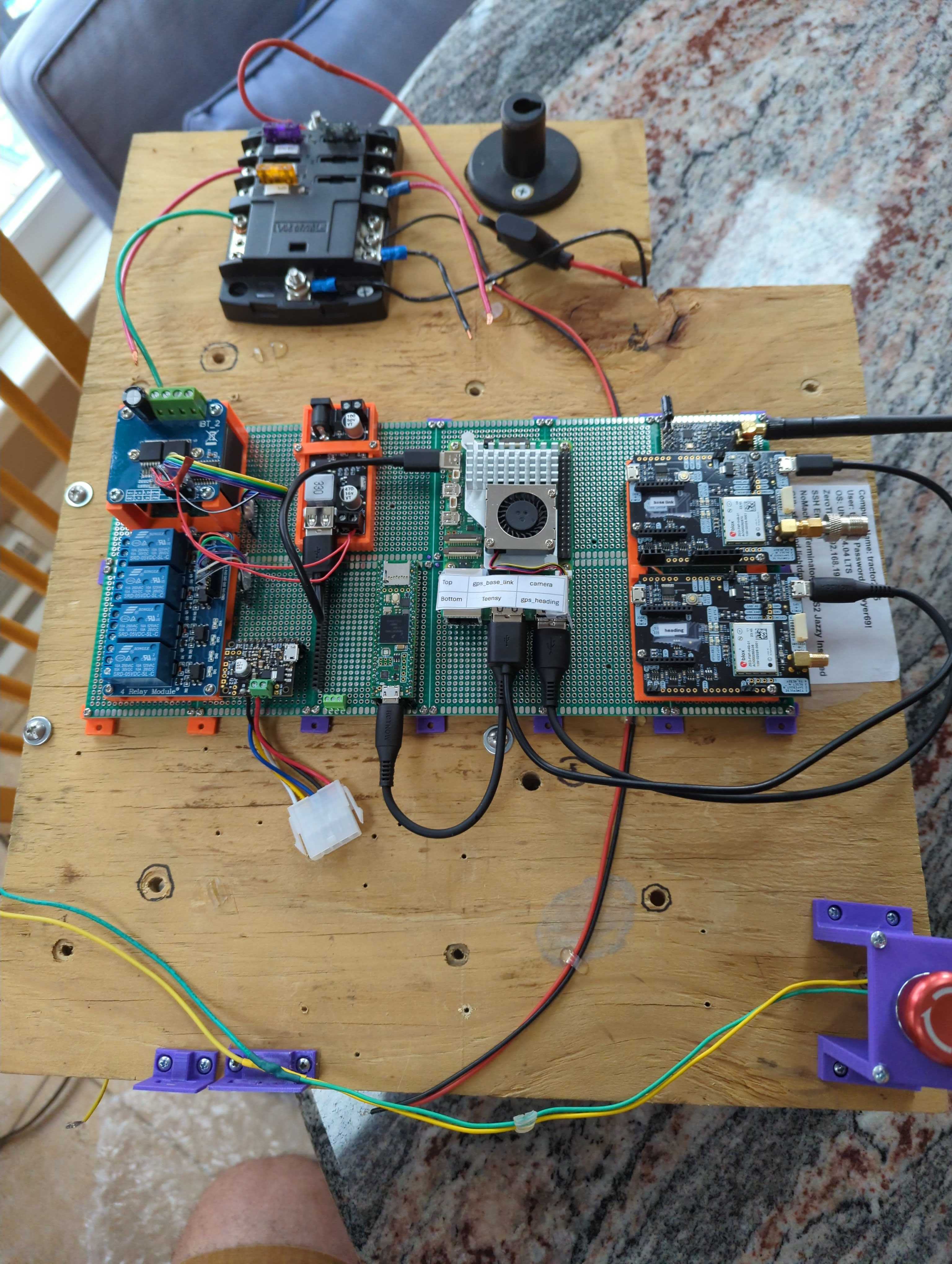
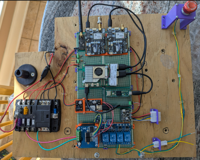
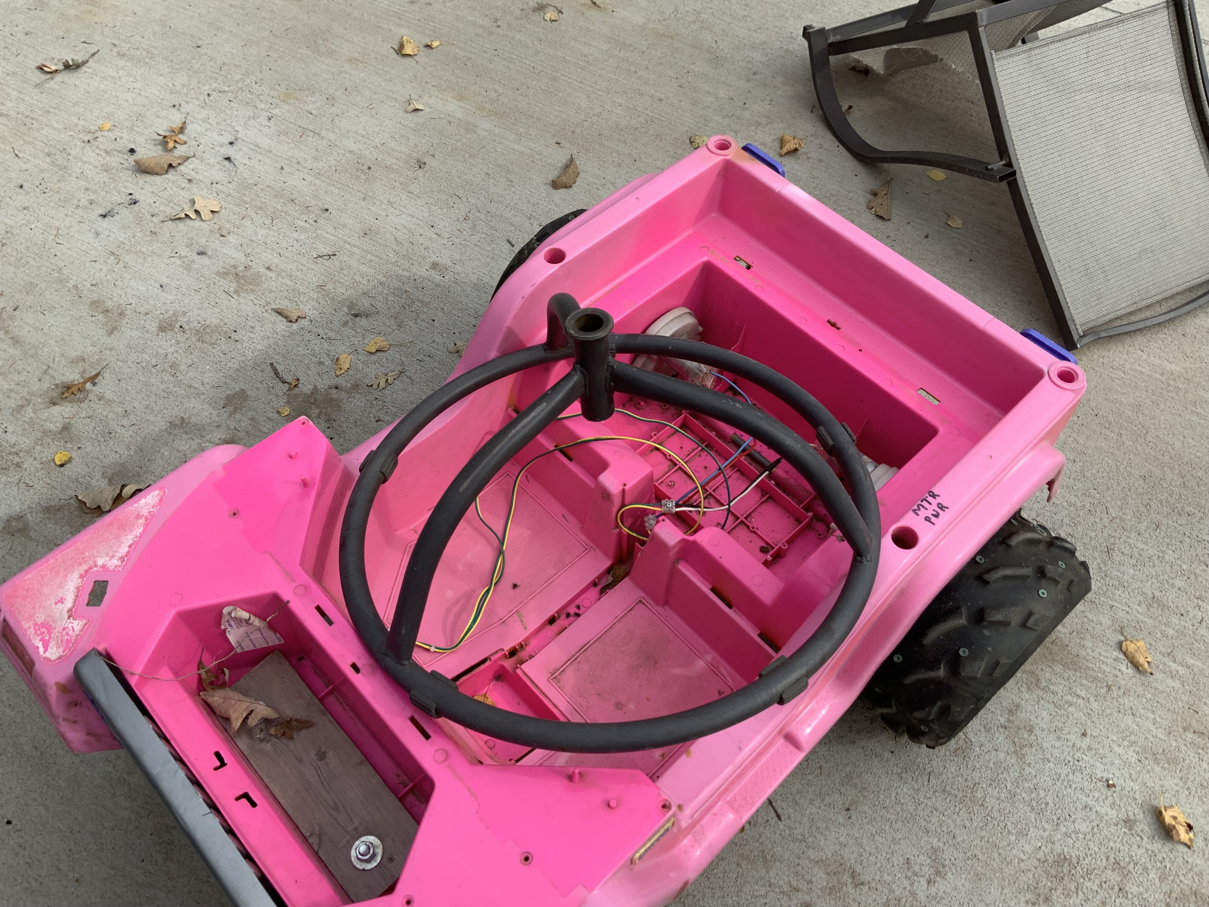
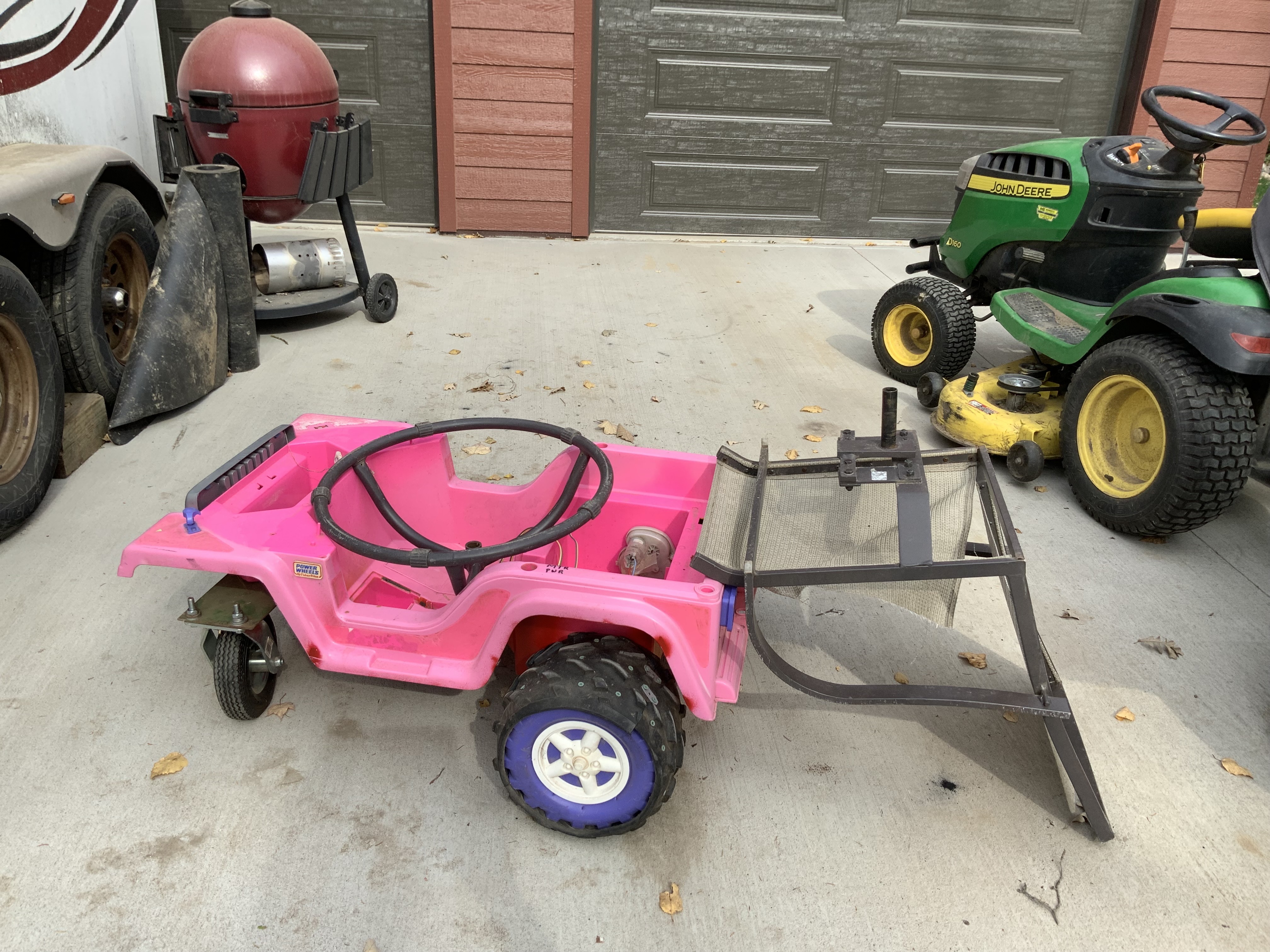
The picture on the left is “DA Beast” riding and controlling an old Barbie Jeep.
So now I can transfer “DA Beast” between the Mini and the Jeep by simply disconnecting and the reconnecting a single Molex connector.
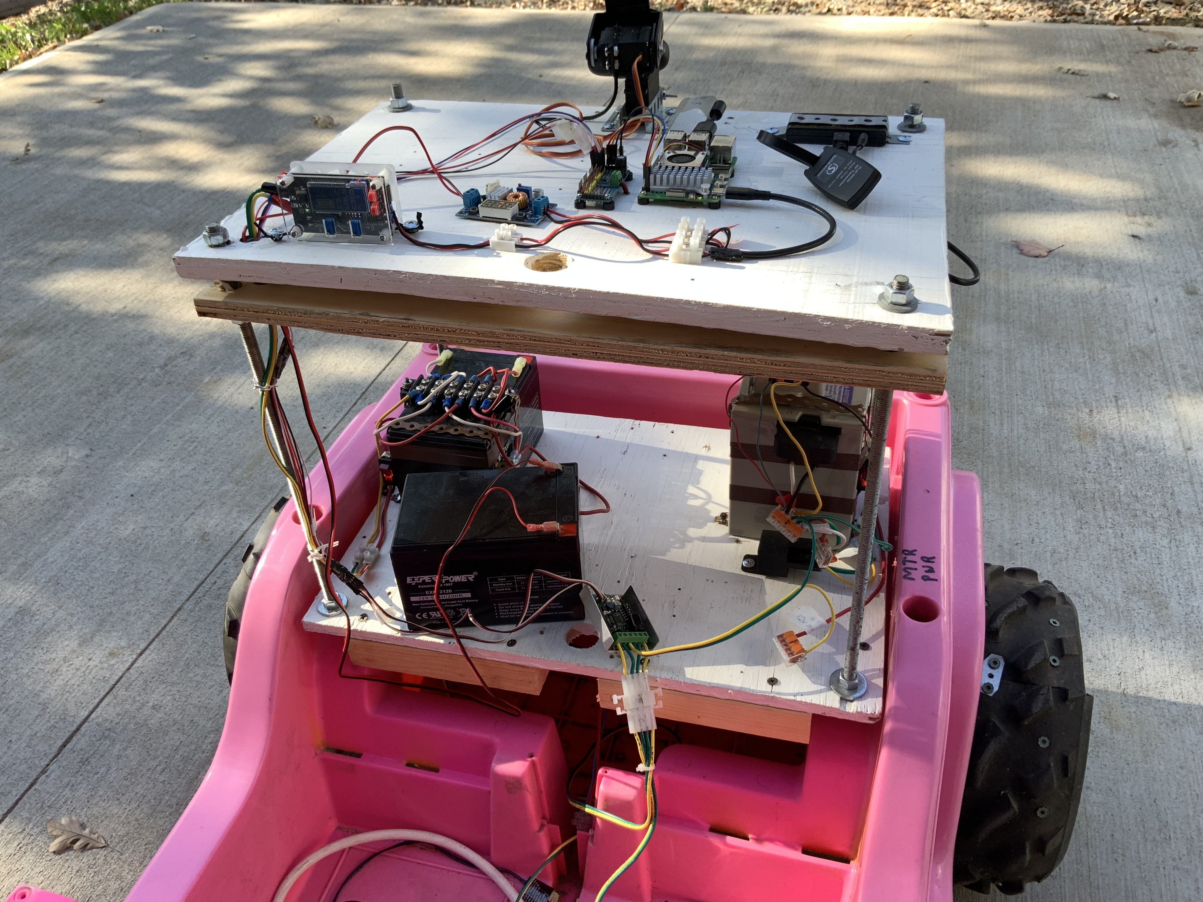
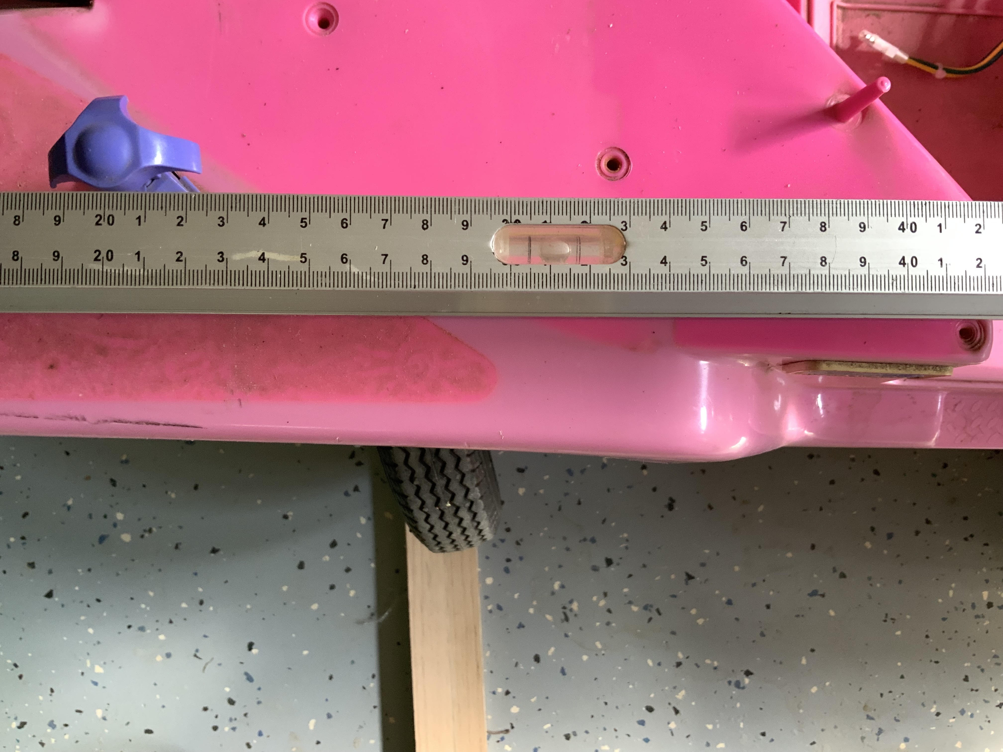
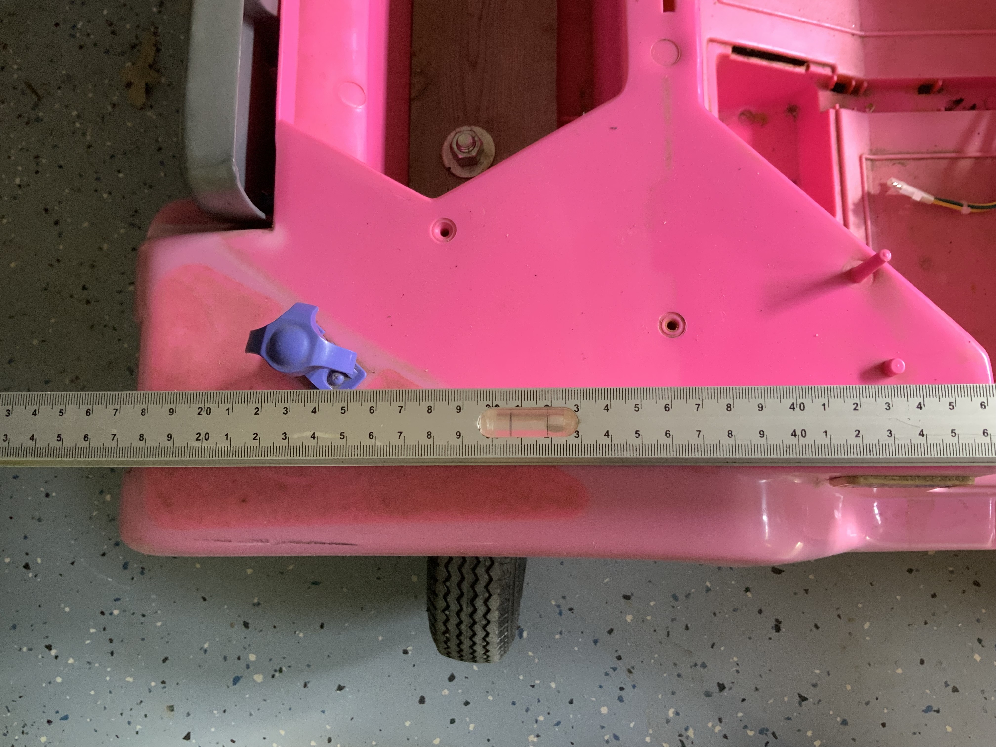
Took “DA Beast” out for a remote drive. A number of issues were very obvious. The screen of the laptop was very difficult to see. Turning left or right was a problem. I noticed the caster wheels would not turn properly. The caster wheel supports where flexing too much. So I’ll have to reinforce that support with some kind of plate inside the Jeep to reduce the plastic from flexing too much. I don’t know how much or how little current is getting to the motors. I want to monitor that better. @Al suggested using a bigger drive battery. Sooo..It’s Back to the bench for some more work. Oh and one other thing. There is a significant (3 to 4 second) delay on the live video.


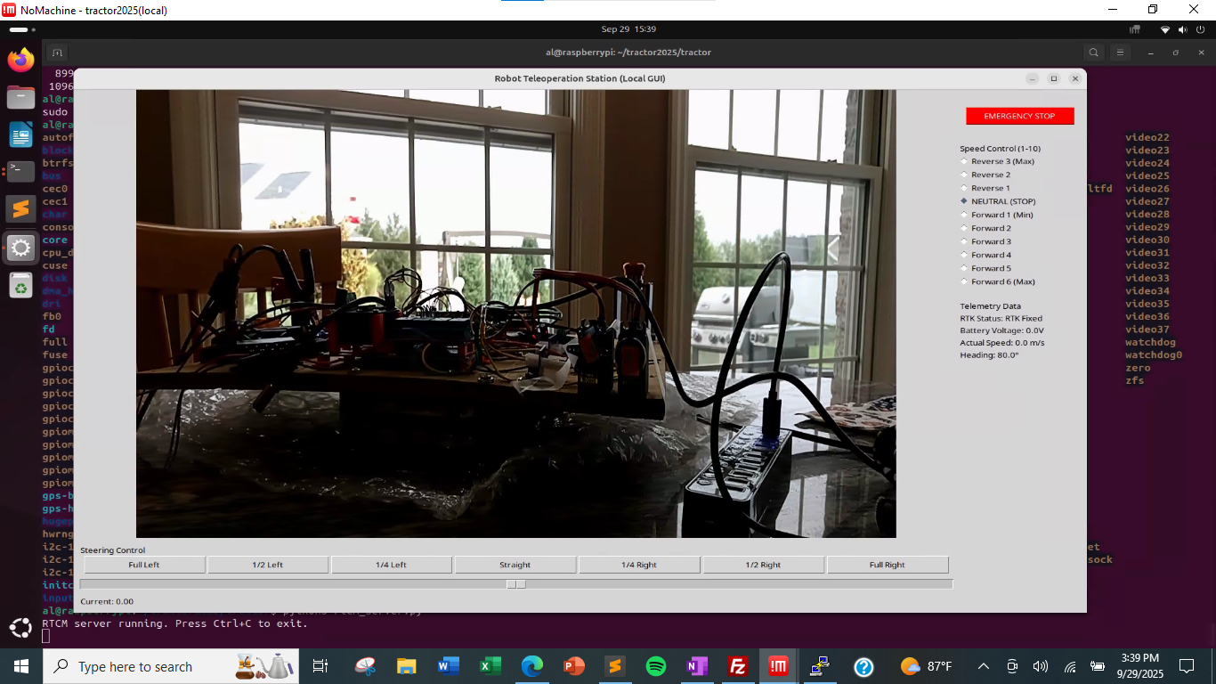
Tweaking my teleoperation screen, still just at the kitchen table. I moved the steering slider under the video on the tkinter screen. I also have the RTK status and heading information along the right-hand side. Battery and actual speed are simply placeholders at this time.
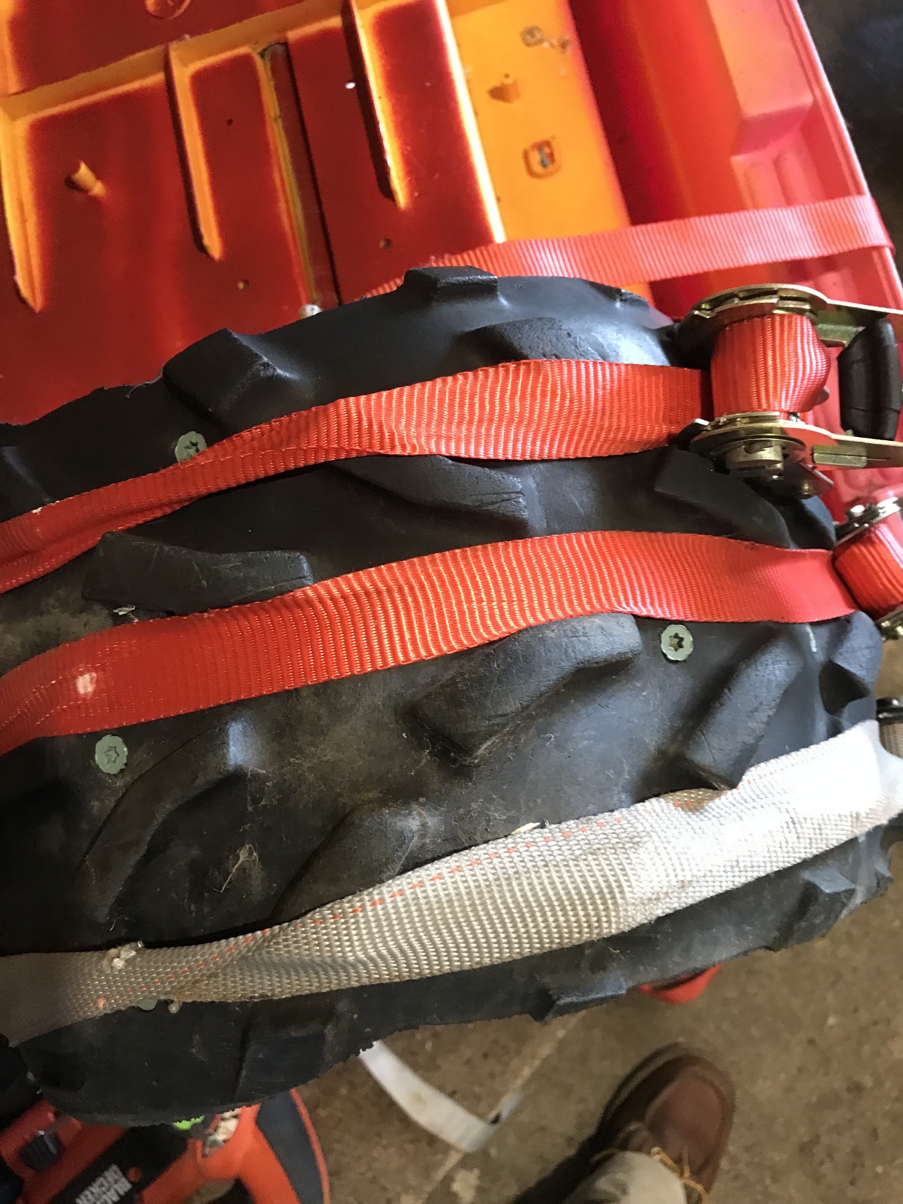
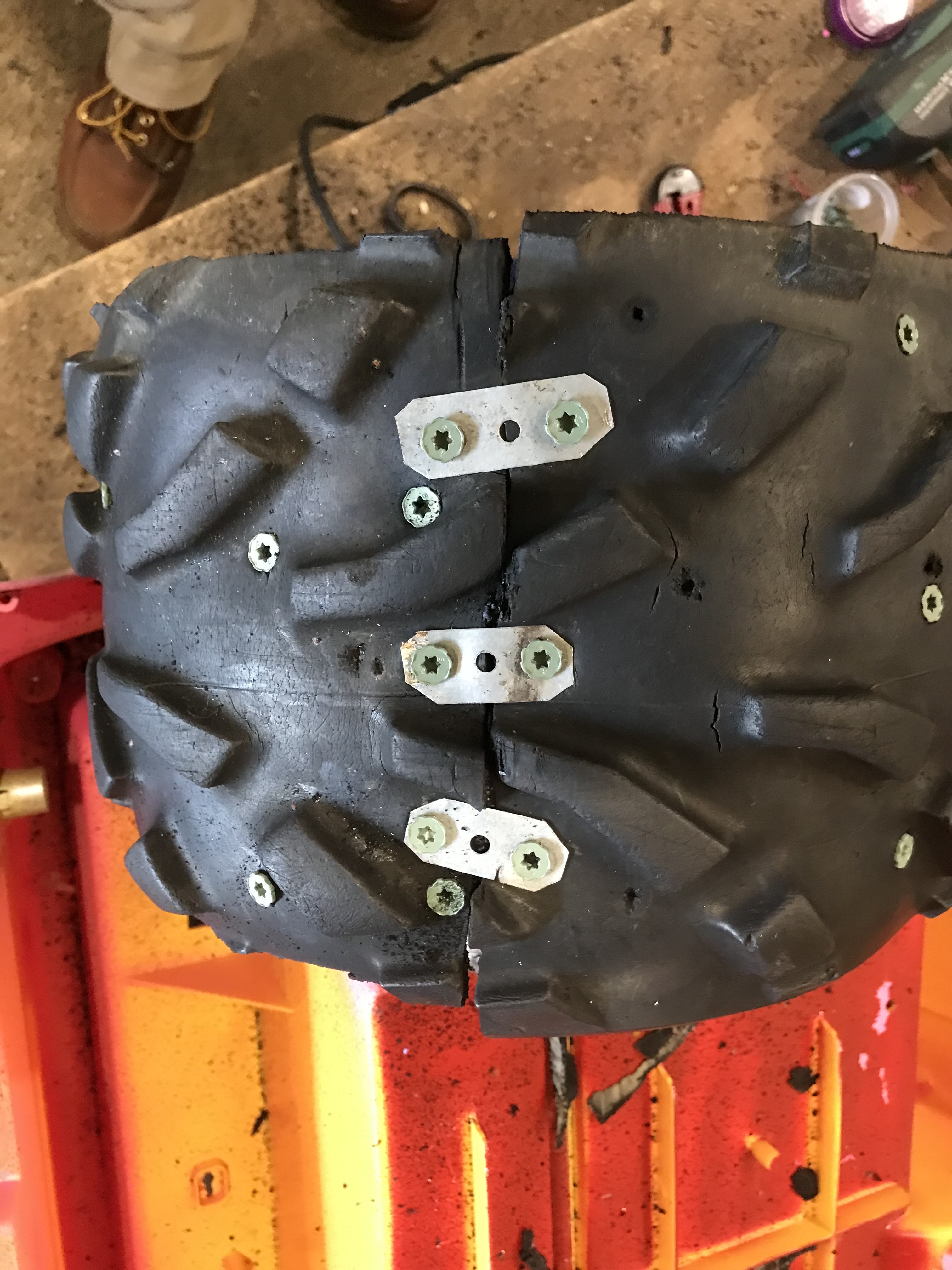
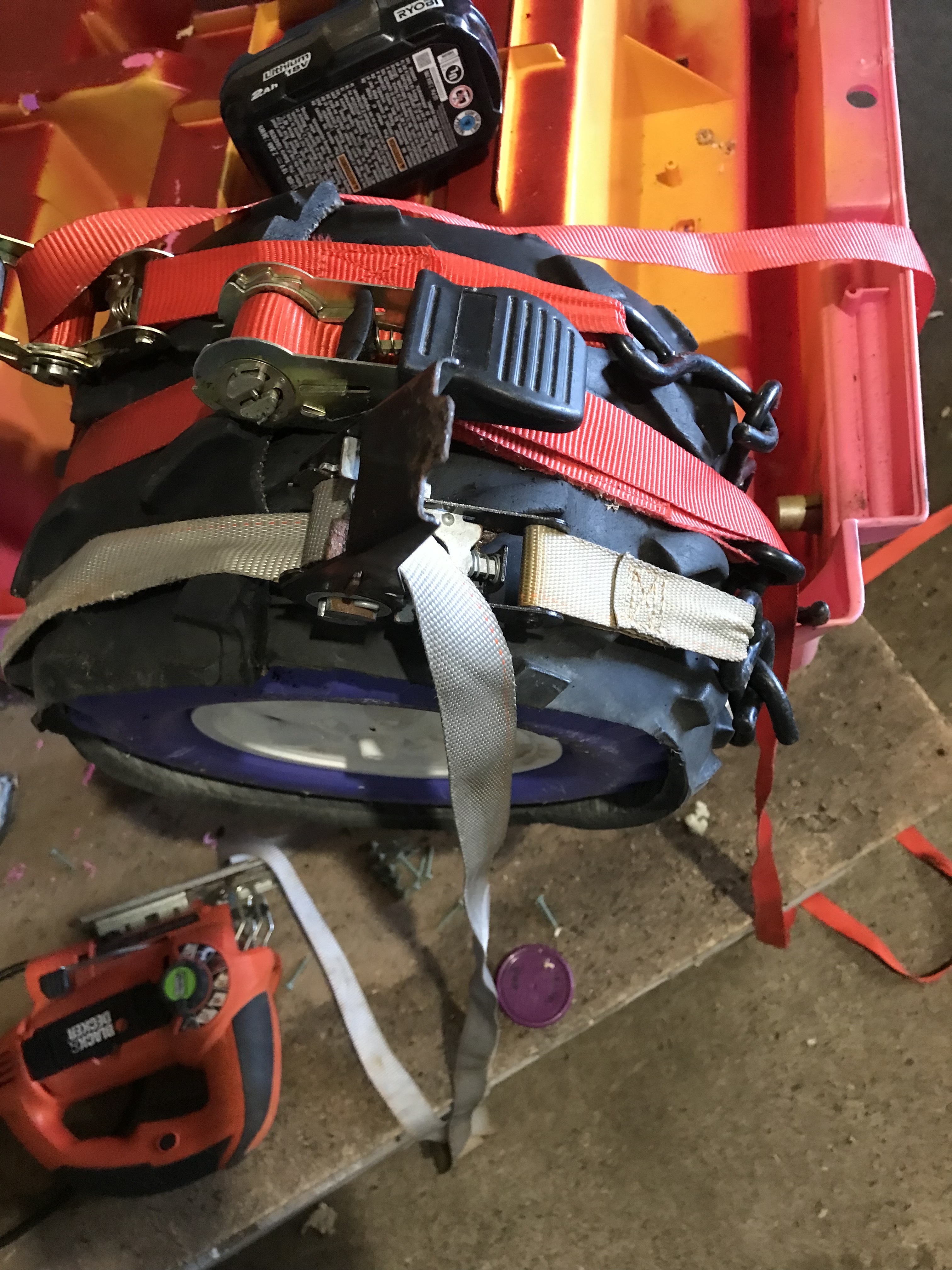
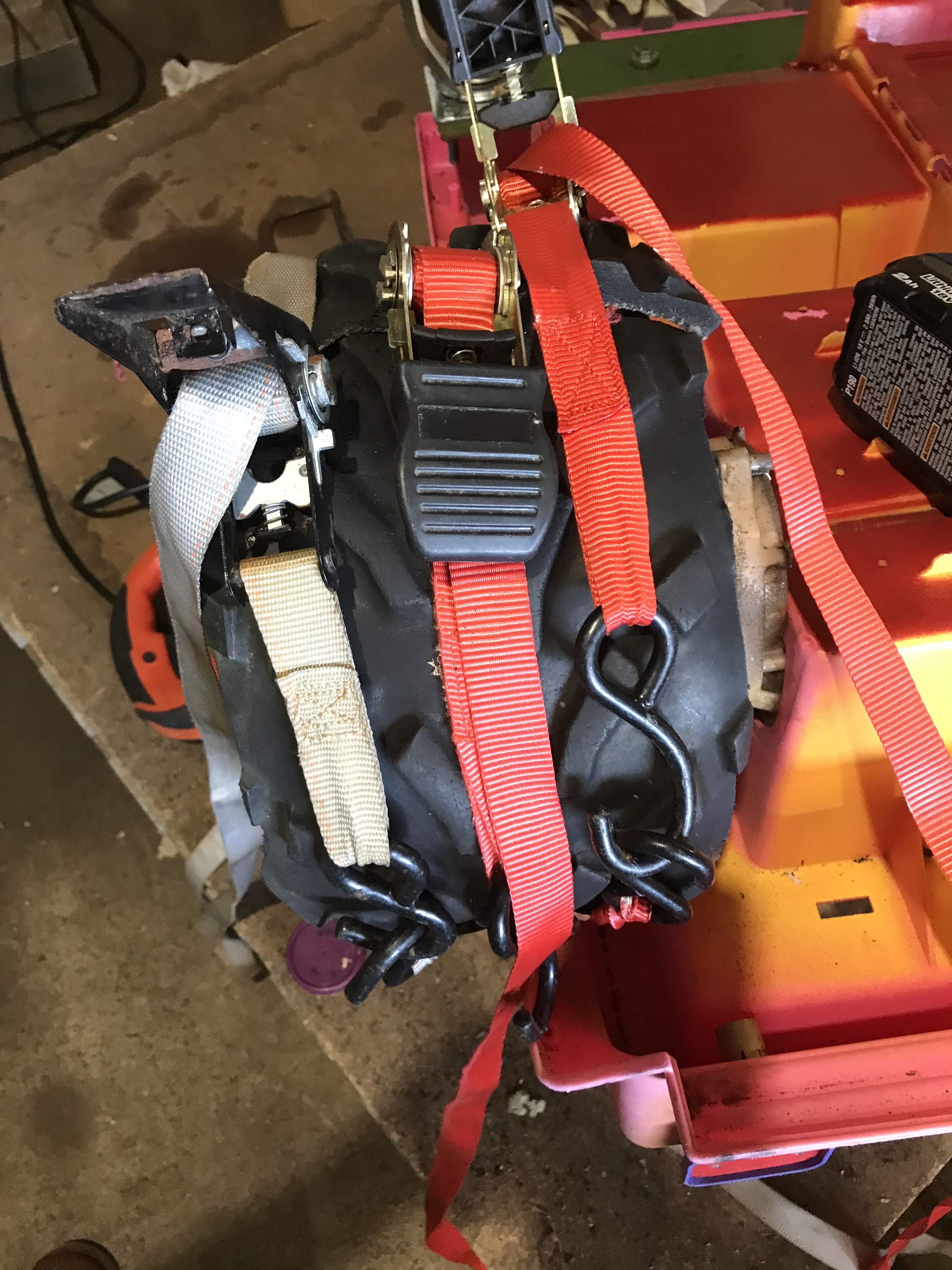
@Bob Hassett Remind us again on Thursday what you did to your wheels for extra traction.

If we go to the index and search for "traction" we get:
http://sampson-jeff.com/RosAgriculture/LawnTractorMeetingNotes.htm#20230831
And it says:
25:00 Al: Asks Bob to go ahead. Bob talks about his Barbie Jeep.
   Adding extra traction strips to the plastic wheels.
Just sayin'...
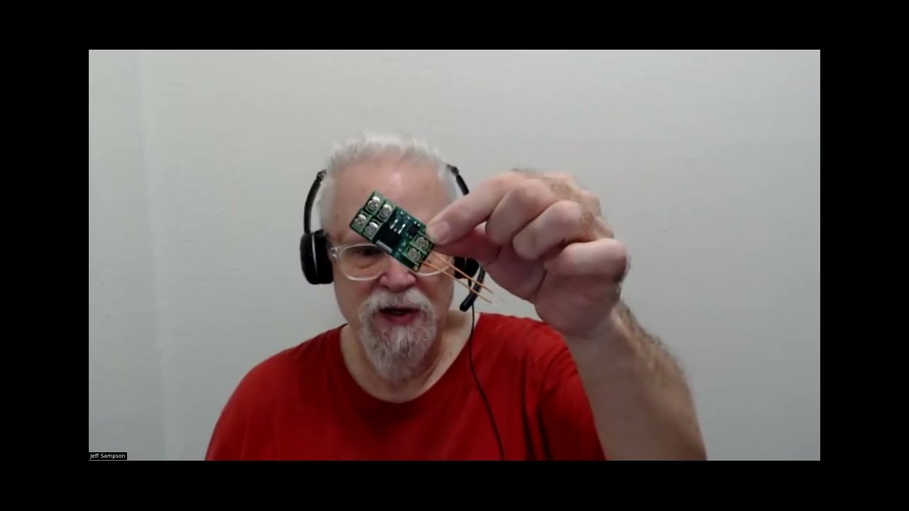
My package from China showed up today. So I have 10 of the new boards. https://www.amazon.com/Driver-dimming-Constant-Current-Module/dp/B0F8RBYH7X
So far these seem quite adequate. I can drive them directly from the 12V battery system. The current is not adjustable. It is set to ~350ma. The first board seems to be set to 310ma. With the high voltage input, I can swap out various high power LEDs. I played with 1W red, 3W orange, 1W white and a 10W white. I can just swap them in and out and all are driven at 310ma. The red and orange LEDs are about 2.0-2.4 volts. The small white LED is about 3.0-3.4 volts. The 10W white needs about 8.5-9.0 volts.
I haven't played with the PWM on the old boards or the new boards. I might do that tomorrow.
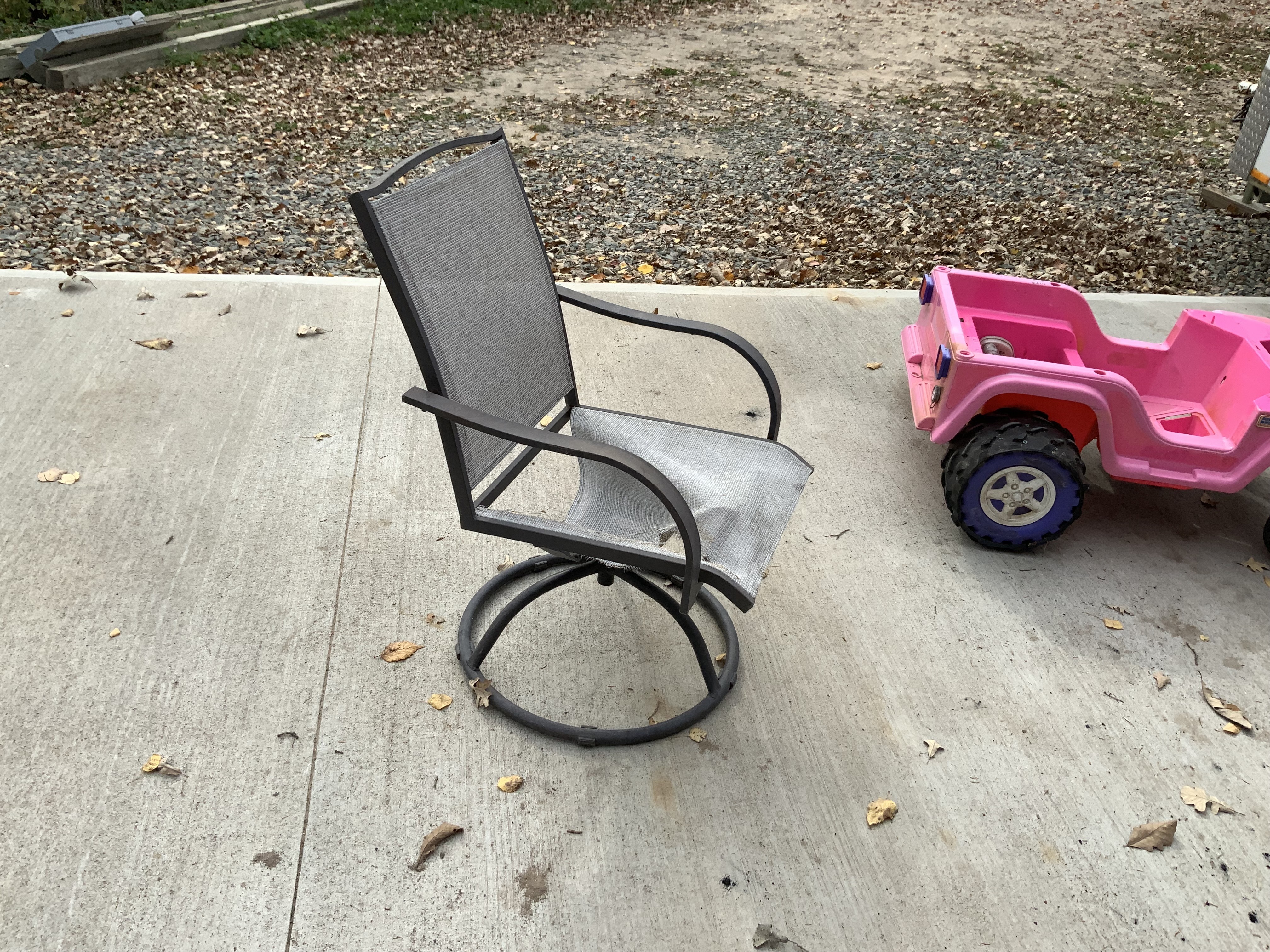
My wife, Nancy, said…why don’t you make a robot out of this old swivel chair. So we tried brainstorming which way to put a turret on the Jeep. Eventually I have to come up with a couple of slip rings to get power to and from the electronics? Anyway it would take some cutting, blocking and custom fitting. I’ll wait until it’s too cold outside. More time to think about it.
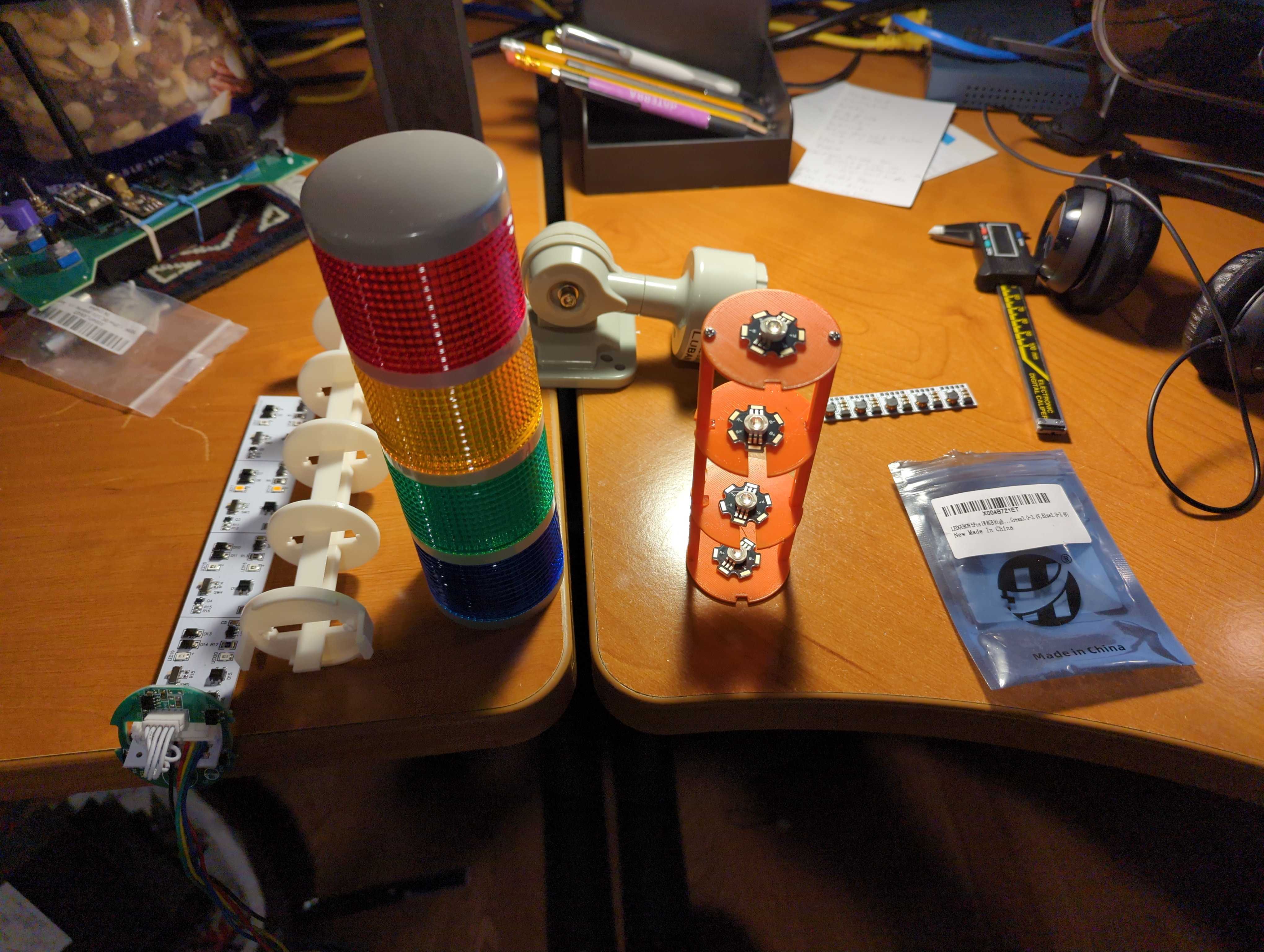
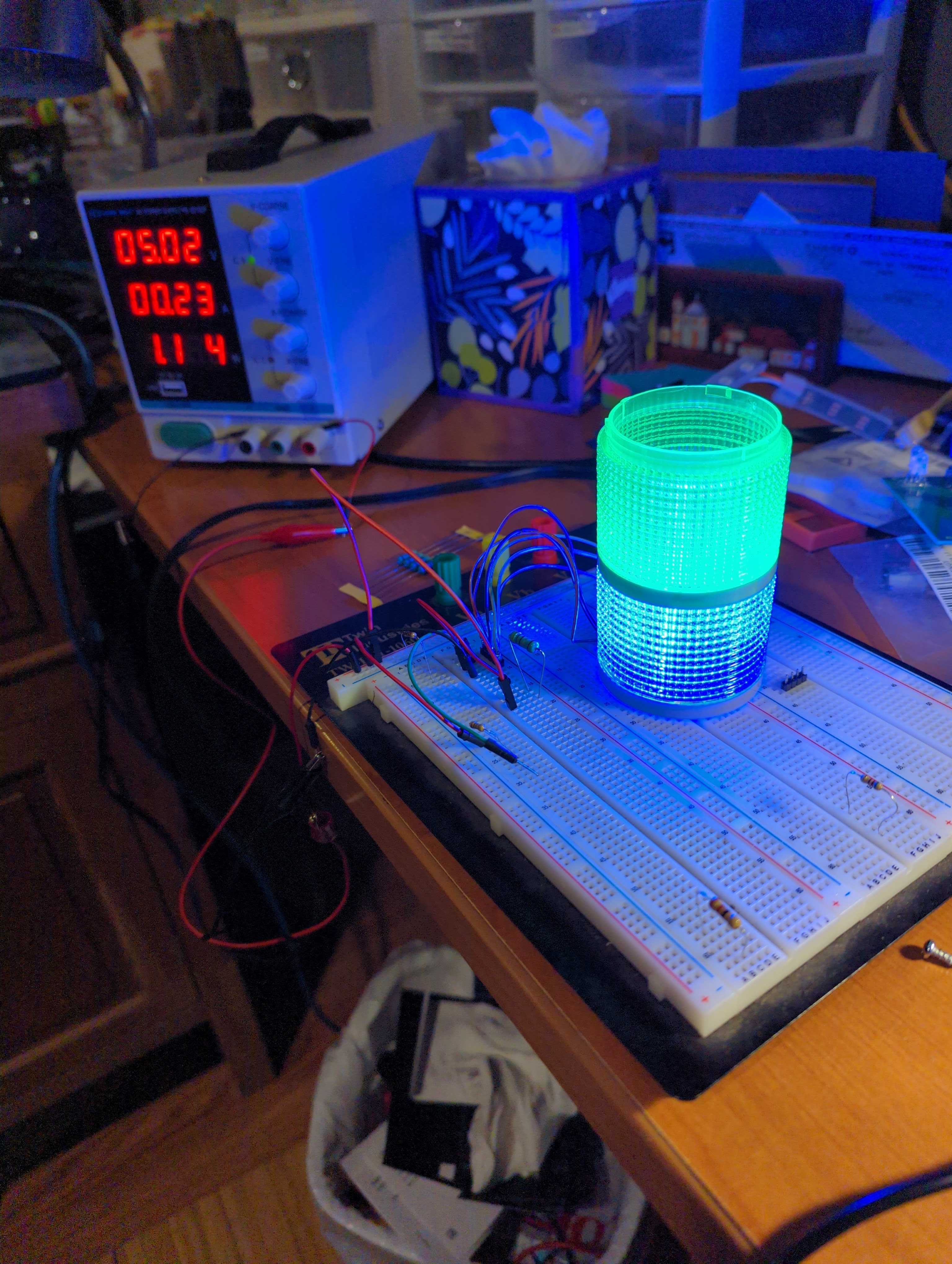
Working on my light using the 1W LEDs instead of the original lights that are too dim for outside. The orange tower helps work out my dimensions since I want to reuse the colored lenses.
*Thread Reply:* Using resistors to mix green (100 ohms) and red (10 ohms) to get yellow.
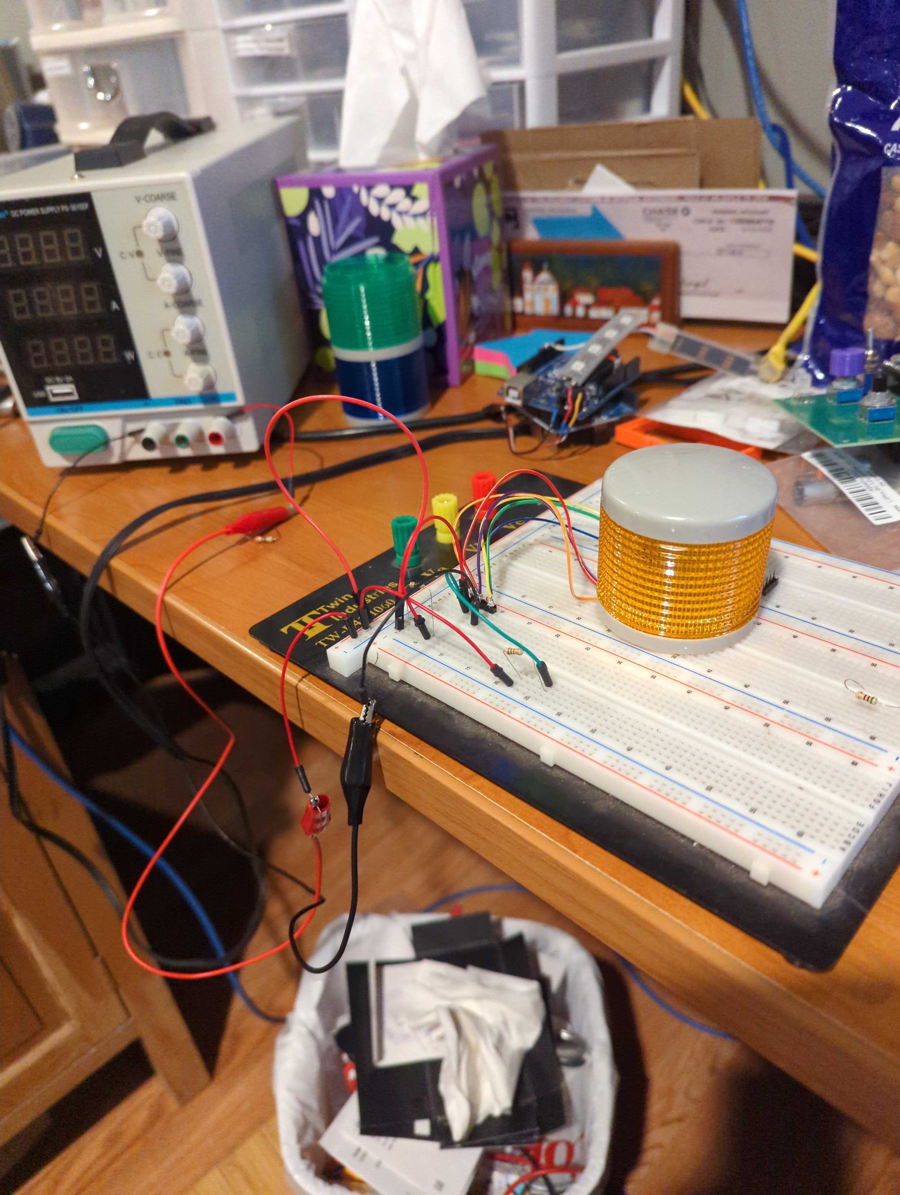
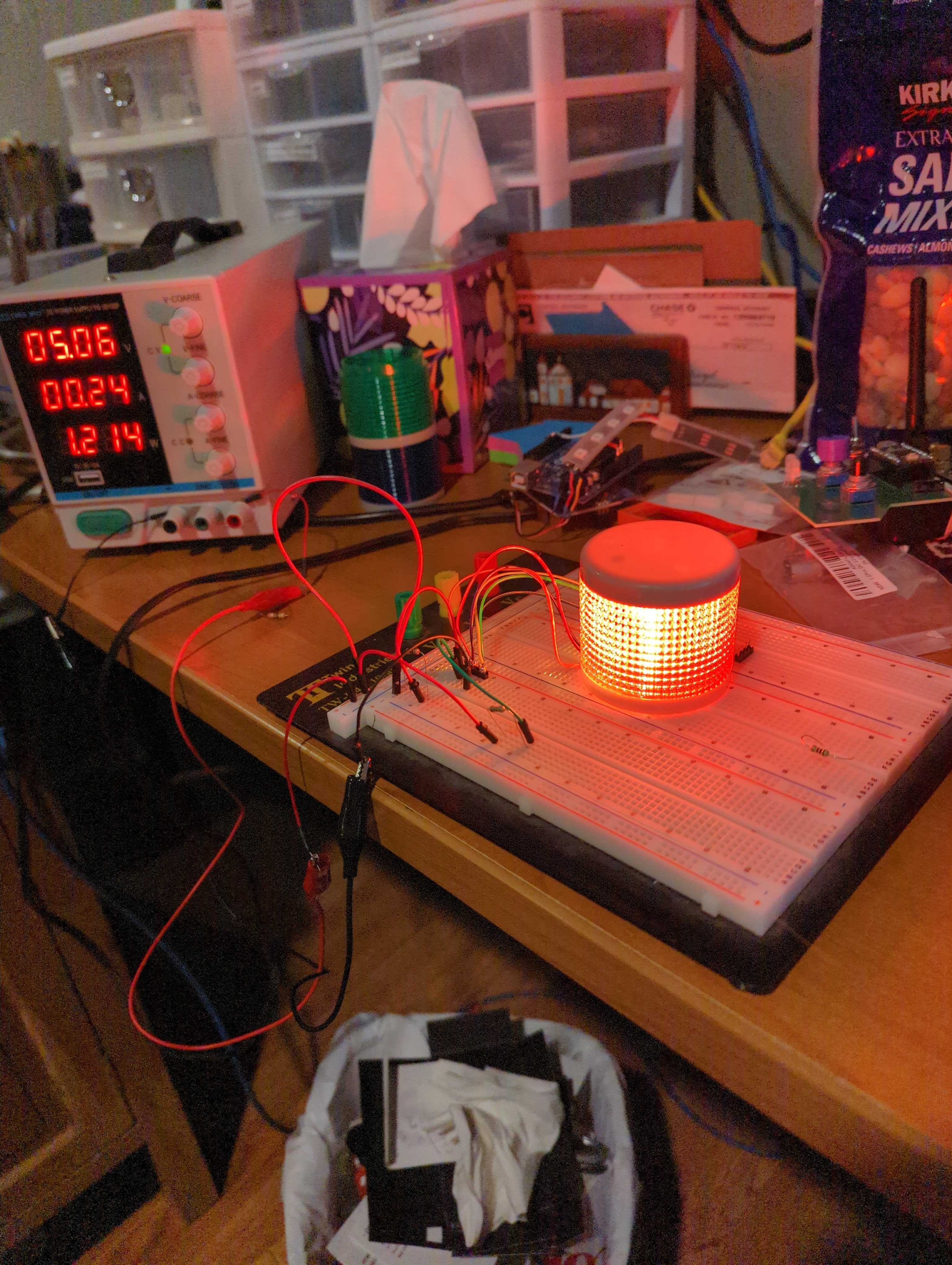
*Thread Reply:* A 4.7 ohm resistor on the blue line, with 5 volt input is showing 0.23 amps usage. I'm using a 1 watt resistor and it seems to be staying cool.
*Thread Reply:* You might try gluing or taping aluminum foil on the top and bottom of each "tower layer". That will stop light from bleeding into the next high layer. And it will reflect and force all of the light to come out the sides.
It looks good on the bench...
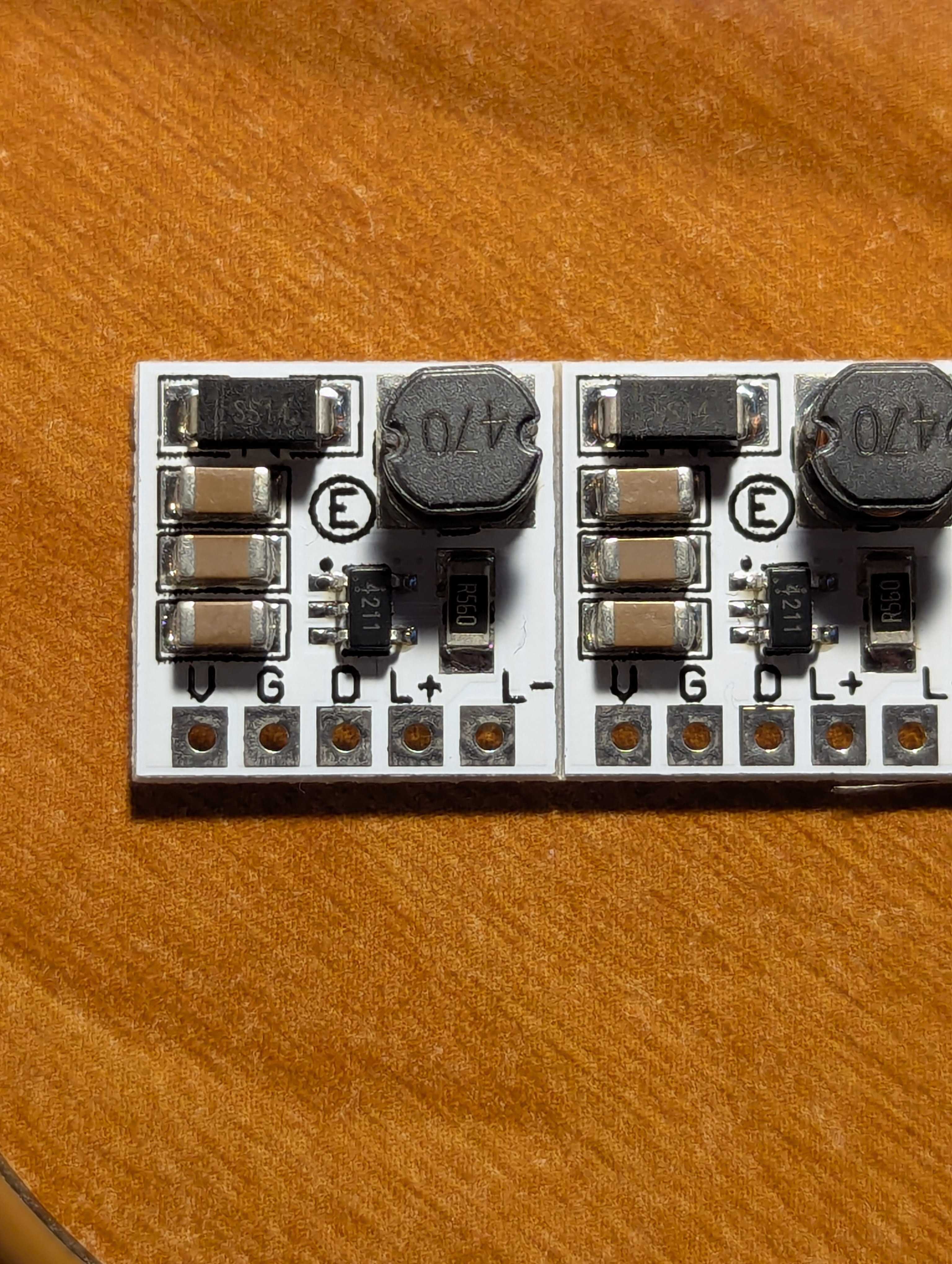
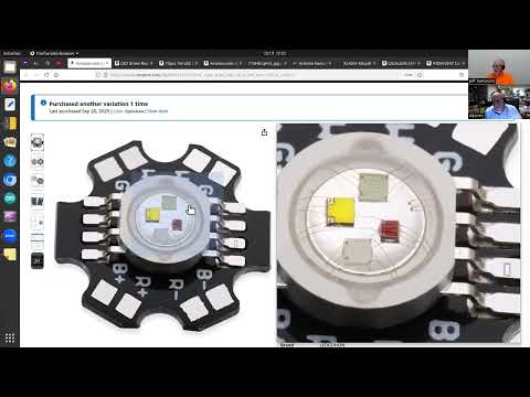
@Al Jones I see from your latest photos that your driver boards showed up.
If you go to Amazon to get your part number (which I think is also silk screened on your boards).
Search YouTube for that and you get this crappy video: https://www.youtube.com/shorts/FQNRswNgnms
If you click the description on that you can extract this link: https://eletechsups.com/eletechsup/LD2635MA-1.rar Product link:https://eletechsups.com/driver-board-c-1_23/ld2635ma-32ch-di-pnp-digital-switch-plc-io-expansion-board-3000vdc-optical-isolation-input-rs485-modbus-rtu-module-p-505.html
That gives some info. If you go to the "Technical Documents" tab you can download a data sheet.
If your board matches all of the photos on Amazon and elsewhere, then I assume your board is set to 200ma output.
*Thread Reply:* @JeffS Thanks for all the help. Yes, they did show up. I had no idea how to use them so I started to use resistors to try and teach myself how to drive these darn LEDs. Hoping with your links I can compare both approaches to driving them.
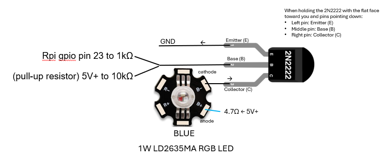
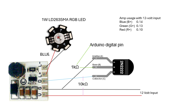
*Thread Reply:* Trying to teach myself how I would drive the LEDs with resistors and an NPN. This is what I have so far. I need to add the additional NPNs to the ground lines.

*Thread Reply:* What you have doesn't appear to be right.
Your diagram and description for "Red" appear to be right. But the other LEDs appear to be wrong. You show all of the cathodes tied together and going directly to ground. They should go to each respective transistor collector instead of directly to ground.
====
Also, you may (or may not) want two separate transistors for the "Yellow" LED.
You probably don't need the 4.7K resistor on each transistor base.
====
Also consider logistics. Looking at the red circuit. It doesn't matter if the resistor is between 5v and anode OR the resistor is between the cathode and the transistor collector. (Since it is just a series circuit.)
So you could solder all of you anodes together and bring out a single 5V feedline. And bring out each individual cathode to a driver board.. Put your resistor next to the respective transistor. That way you don't have solder and resolder resistors inside of your column if you decide to change values.
====
BUT! If you switch to those driver boards then you have to individually bring out both wires for each LED. Or put the driver boards next to the each LED inside of the column. Then just run ~5 volts~ (Whoops. I meant battery voltage) and ground into the column and bring out each PWM line to control each LED.
====
How yellow does it look if you run the red and green at equal intensity for the "yellow" LED? Based on that answer, I will offer a couple more wiring suggestions.
====
Do you want to control the intensity of these LEDs from software? Or just turn them ON/OFF? Or just flash them ON/OFF? I will offer more comments based on your answer.
*Thread Reply:* "...the other LEDs appear to be wrong...", true. That is why I mentioned, "This is what I have so far. I need to add the additional NPNs to the ground lines.".
We can go through the other points tomorrow.
I see if you download the datasheet that it is .rar format. My Linux will not extract that. https://eletechsups.com/eletechsup/LD2635MA-1.rar
I didn't try Windows. But it shows it has:
LD2635MA Manual.pdf
PT4211E23E_EN.pdf
If you search for PT4211 you can find Chinese pdf files. Oh, here is an English version:
https://datasheet.lcsc.com/lcsc/PT4211E23E_C82517.pdf
Let me know if you get the manual extracted...
So it looks like if you put battery voltage into this board and connect a 1W LED it will drive the LED at 200ma. Then if you apply a PWM it will dim between 0-200ma.


@Bob Hassett I pushed my python code up to GitHub that uses Tkinter for my teleoperation screen. Again, this code runs on my RPi 5 where my camera is connected. https://github.com/jones2126/tractor2025/blob/main/tractor/oak-camera/oak_control_tkinter.py
Sharing fyi in case you wanted to look at it.
Info from this week's video meeting.
20251002 ROS Lawn Tractor Automation meeting - Length 1:17:18 This video: https://youtu.be/V5oFH4gl73E
Go to the HTML index to get the description for this meeting: http://sampson-jeff.com/RosAgriculture/LawnTractorMeetingNotes.htm#20251002
======

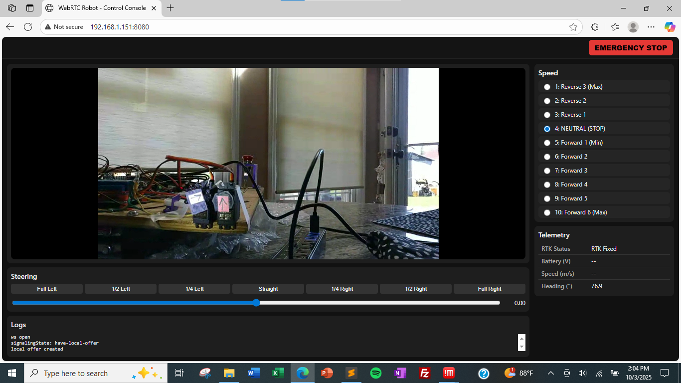
Messing around with @Bob Hassett’s WebRTC. It does seem to be slightly faster than using tkinter and NoMachine (so maybe a 1/2 second delay down to a 1/4 second delay). Code: https://github.com/jones2126/tractor2025/blob/main/tractor/webrtc/server_step6.py
Using HTML would also avoid having to have an HDMI dummy dongle connected. That's not a big deal but makes the electronics board a little cleaner.
https://claude.ai/ definitely helped figure out https://webrtc.org/
@Al Jones How was your experience using Claude? How did you come to choose that one? I don’t suppose you saved the dialog of your request using Claude?
*Thread Reply:* @Bob Hassett I'll send you something tomorrow. My conversation was mostly about getting stuff lined up like I wanted. We can discuss later.
After reading this I think I’ll switch to Claude https://zapier.com/blog/claude-vs-chatgpt/

dag nabit @Al Jones now you gone and got me hooked on Claude. Have not attempted to run on my Rpi5 yet. I want to read it and understand it better. here is a screen shot of my first query results:
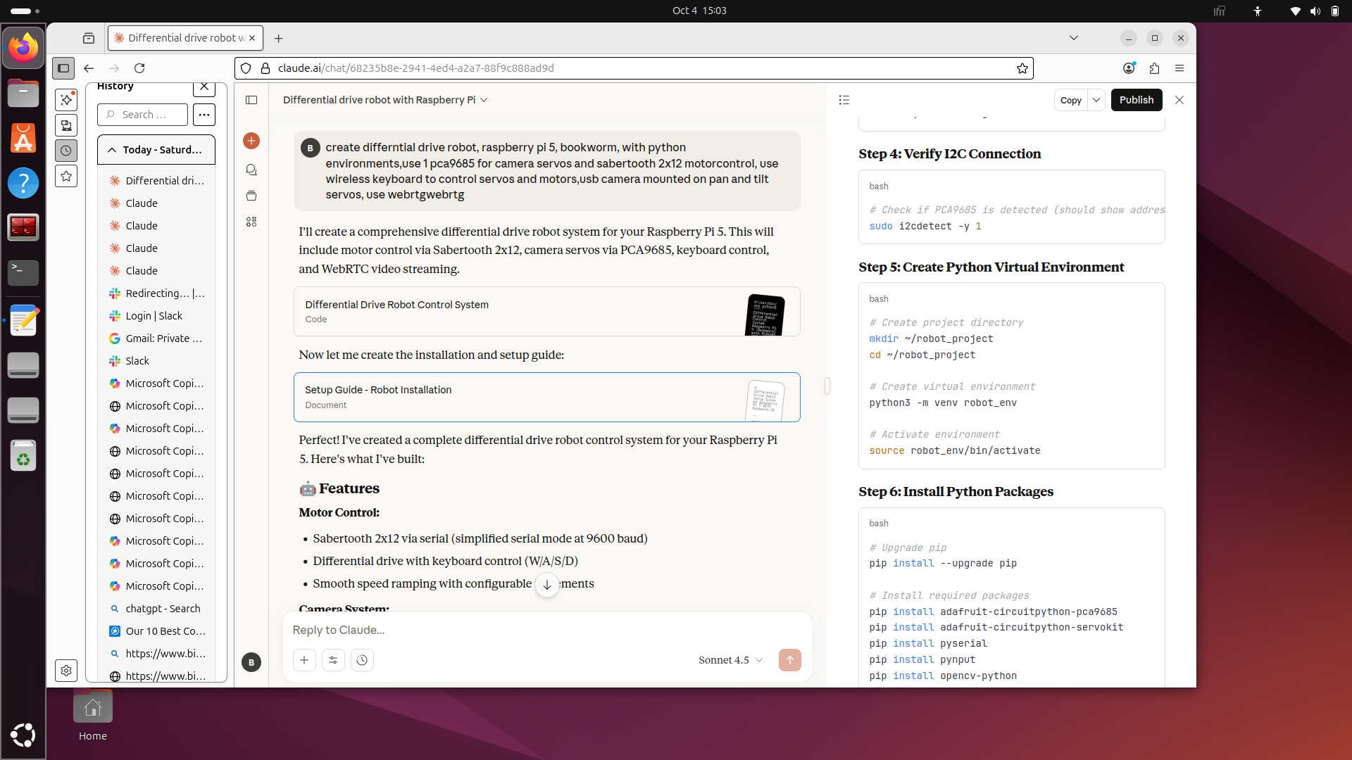
another thing I like about Claude is that it generates a "High Level" of the project;Here's a high-level design and implementation plan for a *differential drive robot* using the following components:
🧠 *Components Used*
* Raspberry Pi 5 running Debian Bookworm * *PCA9685 (PWM controller for servos) * *Sabertooth 2x12 Motor Controller (for brushed DC motors) * *WebRTC (for real-time video streaming/teleoperation) * *OpenCV (for computer vision tasks) * *Differential drive* system (2 powered wheels)
🔧 System Architecture Overview
                   +--------------------+
                   | Raspberry Pi 5     |
                   |  (Debian Bookworm) |
                   +--------------------+
                             |
                             | I2C
                             v
                   +--------------------+
                   | PCA9685 PWM Driver |
                   | (for steering/servo)|
                   +--------------------+
                             |
                             | Serial / UART / USB
                             v
                   +--------------------------+
                   | Sabertooth 2x12          |
                   | (Drive motor controller) |
                   +--------------------------+
                             |
                             v
                    +-------------------+
                    | DC Drive Motors   |
                    | (Left / Right)    |
                    +-------------------+

                             ↑
                      CV + Streaming
                             ↑
                   +--------------------+
                   |  WebRTC + OpenCV   |
                   |  (Teleop + Vision) |
                   +--------------------+
⚙️ Step-by-Step Setup
1. *Basic Raspberry Pi Setup (Debian Bookworm)*
Install Bookworm on your Pi 5 via Raspberry Pi Imager, and configure:
sudo apt update && sudo apt upgrade
sudo apt install python3-pip python3-opencv git i2c-tools
Enable I2C via:
sudo raspi-config
# Go to: Interface Options > I2C > Enable
2. *PCA9685 Servo Control (for steering or camera gimbal)*
Install Adafruit PCA9685 library:
pip3 install adafruit-circuitpython-pca9685
*Example code:*
import board
import busio
from adafruit_pca9685 import PCA9685

i2c = busio.I2C(board.SCL, board.SDA)
pca = PCA9685(i2c)
pca.frequency = 50  # Typical for servos

# Set servo channel 0 to mid position (adjust as needed)
pca.channels[0].duty_cycle = 0x7FFF
3. *Sabertooth 2x12 Setup (UART or USB)*
You can use Sabertooth in *simplified serial mode or packetized serial* via USB.
a. Install pyserial:
pip3 install pyserial
b. Example Python serial control:
import serial
import time

# Connect to Sabertooth over USB (check with ls /dev/ttyUSB**)
sabertooth = serial.Serial('/dev/ttyUSB0', 9600)

def drive_motor(motor_num, speed):
    """
    motor_num: 1 or 2
    speed: -127 to +127
    """
    cmd = bytes([motor_num, int(speed + 127)])
    sabertooth.write(cmd)

# Example: drive forward
drive_motor(1, 50)
drive_motor(2, 50)
time.sleep(1)
Note: Make sure DIP switches on Sabertooth are correctly configured for serial mode.
4. *OpenCV + WebRTC Integration*
You’ll use OpenCV for vision and WebRTC for *live streaming and remote control*.
a. Install opencv-python:
pip3 install opencv-python
b. Install aiortc (Python WebRTC):
pip3 install aiortc opencv-python aiohttp
c. Minimal WebRTC Video Stream Server:
# Filename: webrtc_server.py
import cv2
import asyncio
from aiortc import VideoStreamTrack, RTCPeerConnection, RTCSessionDescription
from aiohttp import web
import av

class CameraStream(VideoStreamTrack):
    def __init__(self):
        super().__init__()
        self.cap = cv2.VideoCapture(0)

    async def recv(self):
        pts, time_base = await self.next_timestamp()
        ret, frame = self.cap.read()
        if not ret:
            return

        frame = cv2.cvtColor(frame, cv2.COLOR_BGR2RGB)
        frame = av.VideoFrame.from_ndarray(frame, format="rgb24")
        frame.pts = pts
        frame.time_base = time_base
        return frame

# Build signaling/offer/answer handlers (example left out for brevity)
# Use aiortc examples as starting point:
# <https://github.com/aiortc/aiortc/tree/main/examples/server>
Alternatively, use the full aiortc video-streaming example and plug in OpenCV + control logic.
5. *Integrating Computer Vision with OpenCV*
You can perform real-time vision tasks like object detection, color tracking, etc.
Example — detect red objects:
cap = cv2.VideoCapture(0)
while True:
    ret, frame = cap.read()
    hsv = cv2.cvtColor(frame, cv2.COLOR_BGR2HSV)
    lower_red = (160, 100, 100)
    upper_red = (180, 255, 255)
    mask = cv2.inRange(hsv, lower_red, upper_red)
    contours, _ = cv2.findContours(mask, cv2.RETR_TREE, cv2.CHAIN_APPROX_SIMPLE)

    if contours:
        cv2.drawContours(frame, contours, -1, (0, 255, 0), 2)

    cv2.imshow('Red Object Detection', frame)
    if cv2.waitKey(1) & 0xFF == ord('q'):
        break
🧩 Putting It All Together
Main loop idea:
# - Read frame from camera
# - Run CV processing
# - Decide motion (left/right/forward)
# - Send commands to Sabertooth
# - Stream via WebRTC
✅ Optional Features
* Add joystick or keyboard remote control (via WebRTC or WebSockets) * Integrate TensorFlow Lite for ML object recognition * Save video locally * Add autonomous navigation logic (e.g., line following)
Would you like a GitHub-ready Python project template combining these components (OpenCV + WebRTC + motor control)?
*Thread Reply:* Just discovered that Claude does not save the conversation in the free edition. One has to copy it and save it some place else. Arg ! That’s not the case with Chat.
@Bob Hassett Take a look at this. I adjusted your prompt and used the 'Publish' feature. Not sure how we can edit this going forward, but willing to give it a try.
https://claude.ai/public/artifacts/7128ff0d-6755-4224-8bba-880dbc7cf599
<iframe src="<https://claude.site/public/artifacts/7128ff0d-6755-4224-8bba-880dbc7cf599/embed>" title="Claude Artifact" width="100%" height="600" frameborder="0" allow="clipboard-write" allowfullscreen></iframe>
This was the prompt:
```# Prompt: Differential-Drive RPi5 Robot with RC first, then WebRTC Teleop
You are my robotics copilot. Design a *step-by-step build plan (phased milestones) for a differential-drive robot using a Raspberry Pi 5 (64-bit, Bookworm) with Python 3.11. Do not use virtual environments.*
When installing Python packages, always install system-wide using pip3 install commands.
If the installer suggests creating a virtual environment, always use the 'break-system-packages' option instead (e.g., pip install --break-system-packages <package>).
*Every step must end with a concise test/verification procedure and pass/fail criteria before moving to the next step.* Include wiring notes, commands, and minimal example code for each phase.
Hardware & constraints
- Drive: *two 12 V DC "Barbie Jeep" motors*
- Motor driver: *Sabertooth 2x12* (differential/left-right)
- Initial control: *radio transmitter/receiver* (RC) FIRST, to prove the drivetrain works safely
- Compute: *Raspberry Pi 5*
- Camera: *USB webcam mounted on a pan/tilt* with two hobby servos
- Servo hat: *PCA9685 16-ch (I2C @ 0x40). Assign channels for pan and tilt* (specify which).
- *No GPS input*
- Later control: *WebRTC (video + bidirectional data) from a browser to the Pi to teleoperate:
- UI must control steering, speed, and camera pan/tilt
- Use two DataChannels:
control(JSON commands) andtelemetry(status) - Start from/align with my example WebRTC script and UI layout; adapt it for a USB camera rather than DepthAI and add pan/tilt* controls.
Deliverables you must produce
*Phase 0 – Safety & power plan*
- Fusing, battery/power distribution, Sabertooth DIP-switch settings for RC mode, E-stop behavior, and neutral-on-boot requirements.
- Bench test to confirm Sabertooth fails safe (motors stop) when signal is lost or Pi crashes.
*Phase 1 – RC-only bring-up (no Pi)*
- Wire the RC receiver to Sabertooth in *RC mode*; calibrate neutral and endpoints.
- *Test:* On blocks, verify forward/reverse, left/right, braking; document trims.
*Phase 2 – Pi setup*
- Use *system-wide package installs* only, not virtual environments.
- Enable I2C; verify *PCA9685* at
0x40withi2cdetect. - *Test: Run a tiny Python script to sweep pan then tilt* servos on the PCA9685.
*Phase 3 – Pi control of Sabertooth (serial mode)*
- Reconfigure Sabertooth for *Simplified Serial* (or Packetized—justify choice) at a fixed baud.
- Wire Pi UART (or a USB-TTL adapter) to Sabertooth S1 (and S2 if needed); include notes about
enable_uart=1, disabling console on UART, and logic-level compatibility. - Provide a minimal Python module:
- Inputs:
steering ∈ [-1..+1],speed ∈ [-1..+1] - Output: left/right motor commands mapped to Sabertooth bytes
- Include exponential or linear mix, deadband, and neutral
- Inputs:
- *Test:* With wheels off the ground, run canned patterns: straight, spin-in-place (if allowed), gentle arcs. Confirm thermal/current draw.
*Phase 4 – USB camera capture*
- Choose *OpenCV (V4L2) or GStreamer* pipeline for ~960×540 @ 30 fps; provide command and code.
- *Test:* Local preview on the Pi; verify frame rate and latency.
*Phase 5 – WebRTC teleoperation*
- Use *aiortc* to serve a browser UI over HTTP and establish a peer connection.
- Video track: use the *USB camera* frames instead of DepthAI.
- DataChannels:
controlJSON schema:
{ "steering": -1..1, "speed_pos": 1..10, "cam_pan": -1..1, "cam_tilt": -1..1, "eStop": true|false }telemetryJSON: at minimum{ "battery_v": float, "speed_mps": float, "note": string }
- UI requirements (single page):
- Steering slider with presets (full L/½ L/¼ L/straight/¼ R/½ R/full R)
- Speed as radio buttons 1..10 (with 4 = NEUTRAL)
- Camera pan & tilt controls (sliders or arrow buttons) mapped to PCA9685 channels
- Big E-STOP button that commands neutral + straight and visibly latches
- Integrate/port features from my sample script (layout, logs, codec prefs, etc.) and add *pan/tilt* handling.
- *Test:* Open the page from a LAN browser, confirm <150 ms glass-to-glass and that all controls actuate the correct hardware. Add a watchdog: if DataChannel idle >1 s, command neutral.
*Phase 6 – Road test checklist*
- Pre-drive checks, E-stop drill, limited-speed proving run, and graduated speed unlock.
- Logging and a basic *black-box* CSV: timestamp, inputs, left/right command, battery V.
*Documentation & runbook*
- A
README.mdwith wiring tables (Pi pins ↔ Sabertooth/PCA9685), channel map, DIP switches, setup commands, service files (systemd), and a *troubleshooting* section (UART conflicts, I2C errors, WebRTC ICE issues).
- A
Coding standards & expectations
- Python 3.11; structure code into modules:
sabertooth.py,pca9685_pan_tilt.py,webrtc_server.py,tests/…. - Use type hints and docstrings; keep each script runnable as a standalone demo for its phase.
- Provide *acceptance tests* after each phase (bullet list), including exact shell commands to run them.
- Keep latency low and fail safe: on exceptions, command *neutral and center steering*.```
An additional link that hopefully shows the code: https://claude.ai/share/632d3bd3-4175-4075-871d-bf8bed7de9ee

@Al Jones leave it to a real robotics engineer to approach this robotics stuff properly rather than my throw it at the wall and see what works. I want to take a couple of days to really digest this stuff. Thank you very much!
*Thread Reply:* You are welcome. I'm hardly 'real' at anything; Just hacking my way through 😵💫
A little testing this morning using the LD2635MA LED driver. I have 12 volts input. I think I will use this for the LEDs instead of resistors. Makes it easier to just have 12 volt input I think.
*Thread Reply:* Are your current measurements between the battery and driver board? Or between driver board and LED.
Was your PWM control pin backwards? Is that why you made a transistor invertor?
*Thread Reply:* Current measurement was the readout on the desktop DC power supply before I moved outside.
Don't know about PWM control. The Arduino pin is set high, then low.
*Thread Reply:* The current on the power supply does not equal the current through your LED. I think if you measure your LED current that you will see ~350ma (for all three LED types).
I would connect the PWM (Dim) directly to the Arduino. (unless that doesn't work)
*Thread Reply:* Removing the NPN (i.e. directly connecting the Arduino pin 7 to the D pin) does indeed work. I was thinking the NPN would provides some isolation to protect the Arduino.
Info from this week's video meeting.
20251009 ROS Lawn Tractor Automation meeting - Length 48:53 This video: https://youtu.be/uxCQwYMUSYY
Go to the HTML index to get the description for this meeting: http://sampson-jeff.com/RosAgriculture/LawnTractorMeetingNotes.htm#20251009
======
Looks like I’ll need a new Rpi5. One of the error messages said “USB… over current” Some how the power management chip DA9091 went bad. We’ve had some nasty power outages or I could have shorted something out when I carried it back upstairs. All 5v and 3v ok. So maybe I can still use it as a low level for something. Can’t use the usbs.😡 I can operate it a little from NoMachine on my laptop. But my servo test programs can’t operate the camera servos.
What is your current power source for the RPi5? What do you have plugged into the USB ports? What were you doing when you got the “USB… over current” message?
*Thread Reply:* I carried it upstairs, stumbled a little. It’s still a little too heavy for me at this time. Got it upstairs. Turned it on battery power and Heard a snap and smelled the step down for the servo control board. I noticed wires were loose and some out of place. And of course I had forgotten to tin the ends on those two wires between the step down and servo driver board. So a strand must have shorted something during the move. I replaced the stepdown. The Rpi restarted but keyboard and mouse didn’t work. I used NoMachine on my laptop and was able to startup menu items like it was headless but it was acting strange. So I flashed a different card and used that to reboot. The screen started going thru the boot up sequence and then froze when it reported the usb ports status. All 4 ports were “over current”. I ran the problem thru Chatgbt, “USB peripherals don’t work” It stepped me thru diagnostics which I followed. In the end It suggested I fried the power management chip DA9091.
*Thread Reply:* Or, one of the devices plugged into USB has shorted out. You could unplug those (either all at once or one at a time). Then see if the main problem goes away.
*Thread Reply:* I will look in to it. Also I’m going to check every wire and ground.

Info from this week's video meeting.
20251016 ROS Lawn Tractor Automation meeting - Length 1:01:34 This video: https://youtu.be/po05g40dmko
Go to the HTML index to get the description for this meeting: http://sampson-jeff.com/RosAgriculture/LawnTractorMeetingNotes.htm#20251016
======

I was attempting to load a new flash card for RPi. There is mention to Raspberry Pi Connect. Has anybody tried that? I didn't dig into it. https://www.raspberrypi.com/software/connect/

*Thread Reply:* Have not tried it since I use Ubuntu, ZeroTier and NoMachine. It looks like a smooth solution if you use the RPi OS, not Ubuntu.
*Thread Reply:* It popped up for me as well when I downloaded the latest Rpi OS. Once my hardware is setup I want to compare it with NoMachine. I’m just concerned about security. The possibilities..?
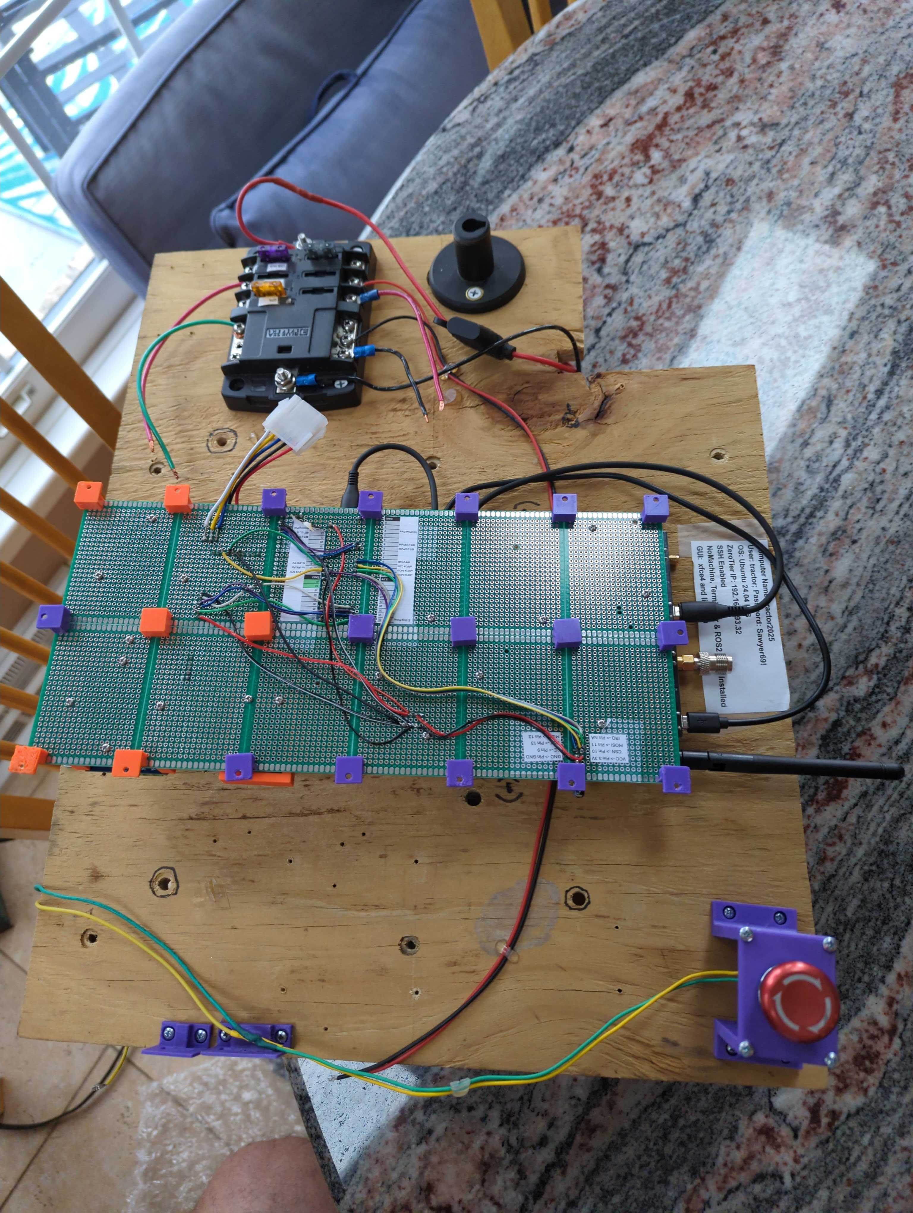
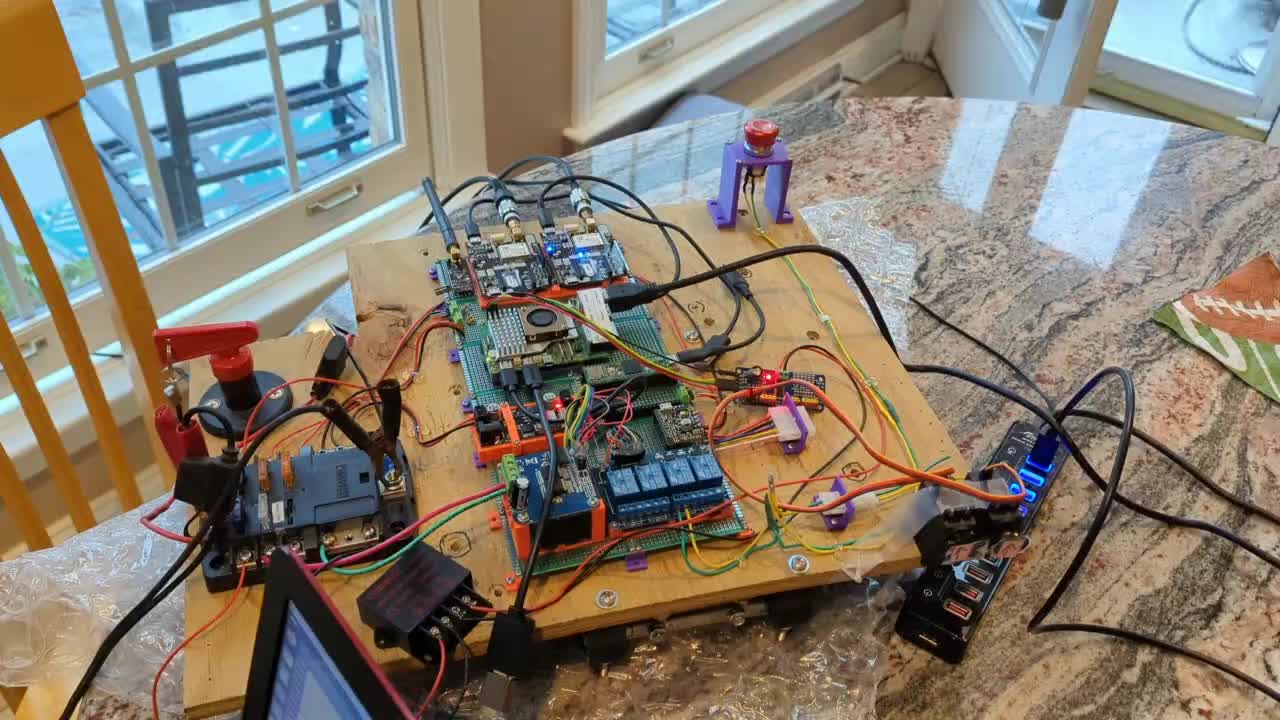
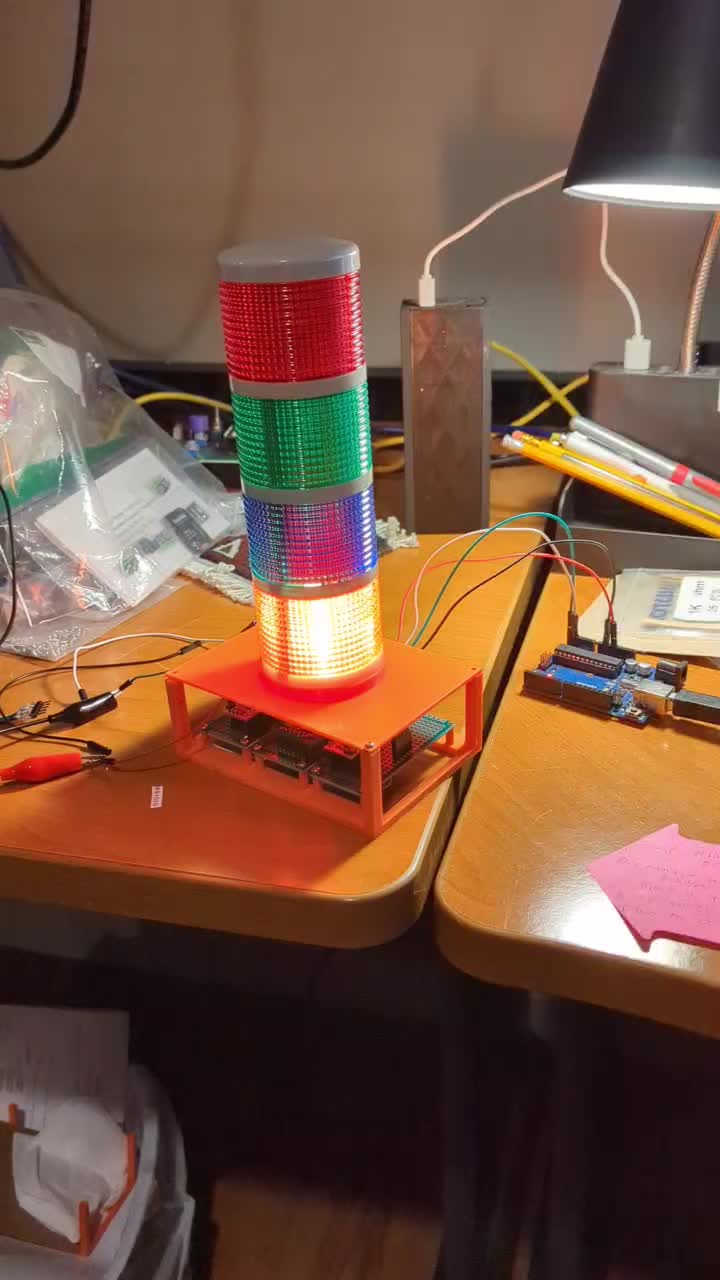
Working on getting the light tower connected to the RPi on my electronics board.
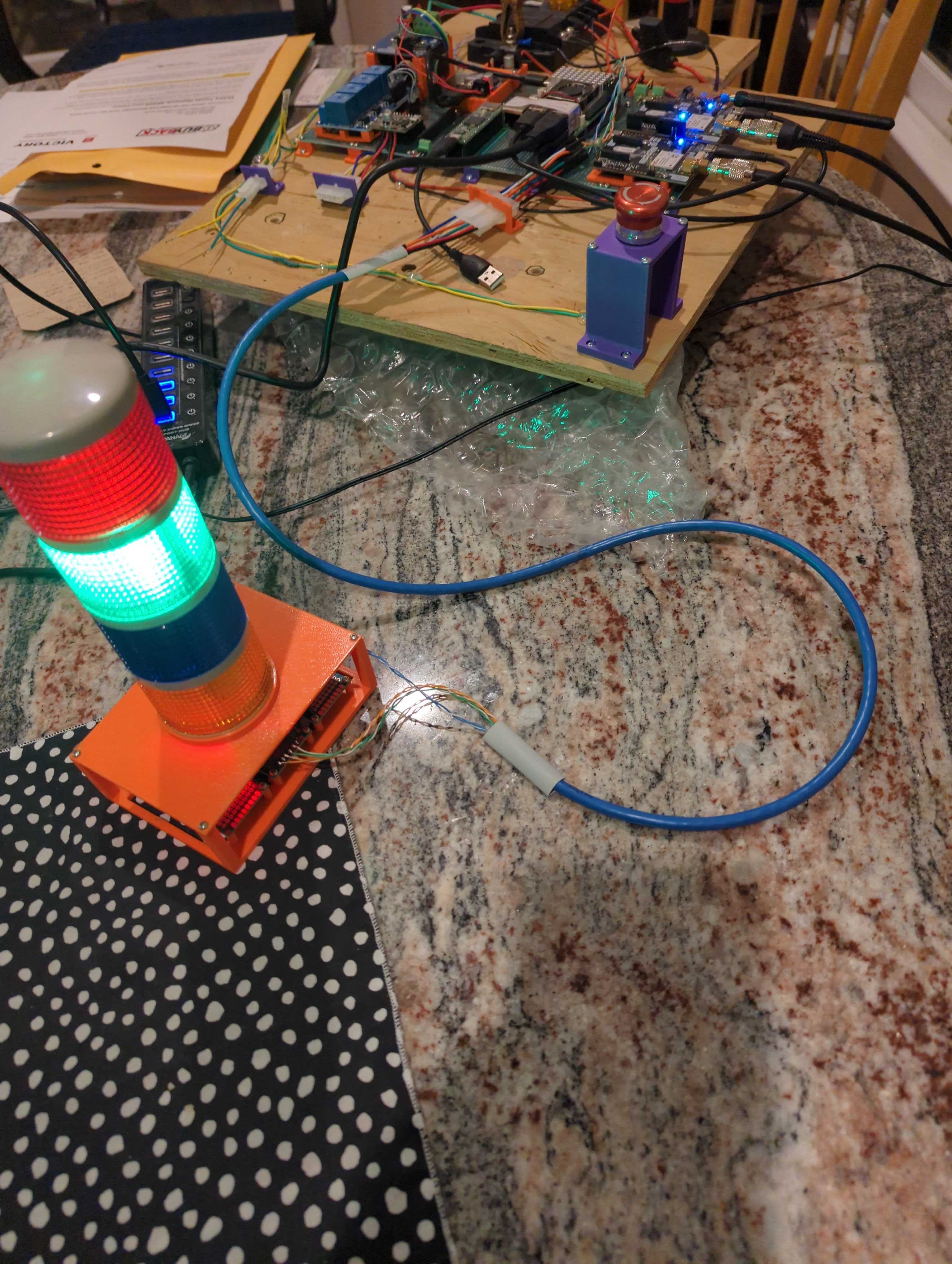
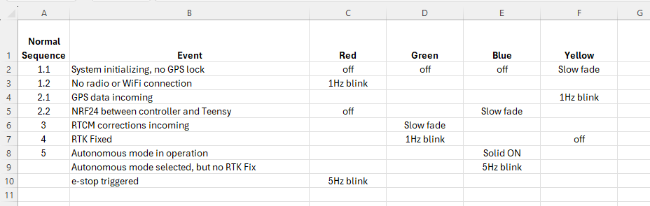
Thinking through how I want to use the LED light tower. These are the events and light statuses I'm considering.
Info from this week's video meeting.
20251023 ROS Lawn Tractor Automation meeting - Length 42:05 This video: https://youtu.be/07l2tXR1VbA
Go to the HTML index to get the description for this meeting: http://sampson-jeff.com/RosAgriculture/LawnTractorMeetingNotes.htm#20251023
======

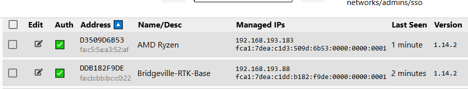
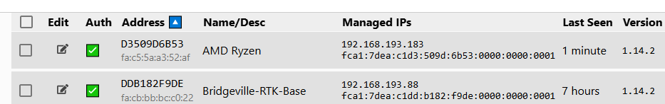
My RTK Base station is not reporting this morning. Looking at the ZeroTier portal it shows it stopped reporting about 1 a.m. (i.e. 7 hours ago). My assumption is my 3 year old, lead acid battery, isn't storing enough energy to get through a few colder, cloudy days. I will wait a few hours for the sun to hit the solar panel and see what I can learn then.
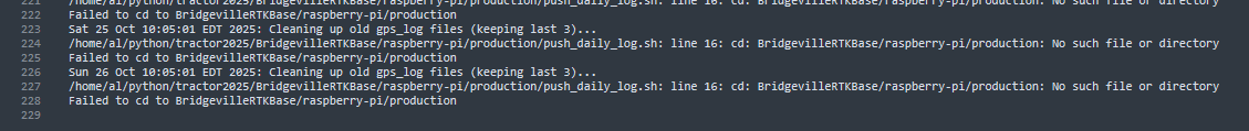
Actually, it came back online while I was posting this. The sun is up and it's a bright day so the RPi is getting enough volts to fire up. Unfortunately, it looks like my download scripts are not working correctly. Maybe due to some folder reconfiguration I did on GitHub.
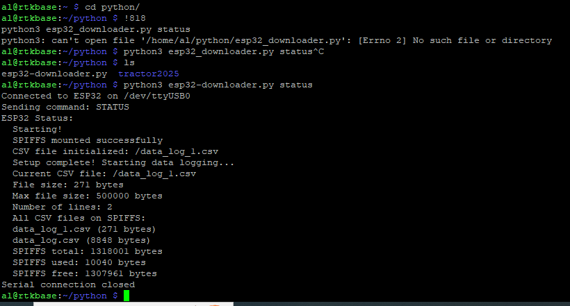
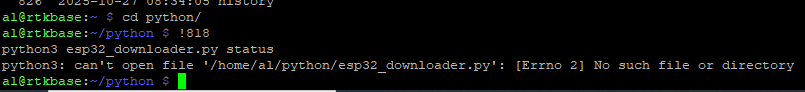
Trying to get status of the ESP32... that did not go well 😞. Where the heck is my .py script?
Found it. Typo in the name. Dash not underscore.
Bummer, now it seems to have gone down again. Unstable 😞
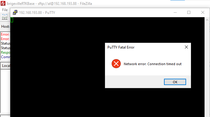
I got back in, and am trying to pull data off the ESP32. It would be useful to know what voltage is being reported in the battery, but FileZilla is now struggling to connect. I must be right on the cusp of acceptable voltage.
Well I got a few records downloaded from the ESP32. The battery is charging, so its unclear what its real voltage was when it failed. I need to wait till this evening and do a bit more monitoring then.
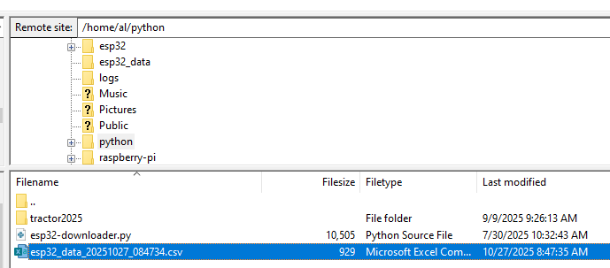
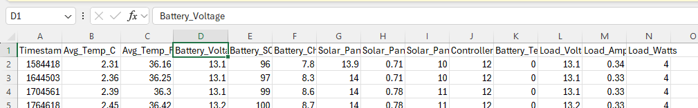
@Al Jones Do you have several days (weeks) of battery voltage, solar charge controller status? What do those look like if you plot them out?
One quick solution would be to only run the GPS when you need it. Unless you need/want GPS correction 24hrs/day. Maybe even add a timer so the GPS it is only running from 7AM to 9PM (or whatever your preference is).
@JeffS Q: Do I have several days..of.. status? A: Not really. The file download was programmed to occur at 6am and since the battery charge was dropping off ~1am the historical logs are not available. I've since changed the timing on the process to download in the evening. I know the drop off occurs in the early hours because ZeroTier VPN shows when it last connected.
"...Maybe even add a timer...", that is a good solution. I just have not gotten around to it. Your RTC experience will be helpful since I am using an RPi 3 in my setup.
Definitely a learning experience to have a remote device running on battery in an unconditioned space.
Making some progress. I’m using carpet tape under switches and lever Wago nuts to help hold them in place. Next is to extend the short wires in what looks like rats nest of wires. My shopping list continues to grow, includes more Molex connectors to replace the Wago lever nuts.

Info from this week's video meeting.
20251030 ROS Lawn Tractor Automation meeting - Length 40:27 This video: https://youtu.be/Mr7VjgyXdvc
Go to the HTML index to get the description for this meeting: http://sampson-jeff.com/RosAgriculture/LawnTractorMeetingNotes.htm#20251030
======
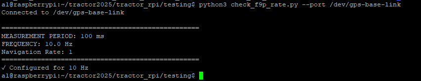
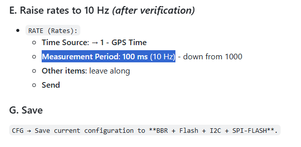
I mentioned F9P 20 hz on the call. I'm going to stick with 10 hz.
Going back and checking my documentation (tractor2025/tractor_rpi/f9p) I see I set the F9P's to 10 hz. I also checked the UBX-CFG-RATE via a script.
We are going to skip the video meeting this week. My only update is that I see there are ways to speed up the sample rate for my DS18B20 sensors. But maybe only with Arduino libraries instead of using Python under Linux.
Info from this week's video meeting.
20251113 ROS Lawn Tractor Automation meeting - Length 56:18 This video: https://youtu.be/xvfUc_zWldc
Go to the HTML index to get the description for this meeting: http://sampson-jeff.com/RosAgriculture/LawnTractorMeetingNotes.htm#20251113
======

Sort of interesting - tachometer hookup for lawn tractor
https://youtu.be/1a_lhJRtWSo?si=kyWsfahe6AUVyhko

*Thread Reply:* Installing a tach could be usefull in determining if the engine is working too hard for some reason!
Found this about Webrtc, really helps me understand the technology. Still have to get more familiarize with all the terms, but a good starting point.
https://youtube.com/watch?v=Ivh8eps-Tic&si=kXBNskeKIgf6cbeT

Another WebRTC link. This time for a Raspberry Pi.
https://wizzdev.com/blog/streaming-locally-and-globally-with-raspberry-pi-using-webrtc/
I tried WizzDev way of installing but ran into problems. Problems I didn’t understand. So I cheated and used ChatGPT. I got a good build and am ready to start some of the recommended examples. Btw I copied the conversation to a Now I’ll try building on iPad.
@Al Jones I’ve got webrtc-Janus loaded on my Rpi 5 and ready to send a “message” Now I’m trying to set up my iPad and robot Rpi5 for two way comms and video. Soooo do use a dedicate web page or ?
@Bob Hassett It's been a while, but this was my first attempt code just to get video showing up on a web page.
*Thread Reply:* Thanks for the tip of using ChatGPT! Amazing how that works!