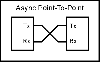
Figure 1a
Previous | Index | Next
Serial Interface Techniques
Serial communications in one form or another have been around long before computers were invented. The serial interface was created due to a need to send information over a distance with one or two wires. I assume it would be fair to say that telegraph was one of the first serial communication devices. The telegraph (in conjunction with Morse Code) allowed communication over great distances. It is also very benifical to use a serial method to send information by radio communications. The early radios used the same Morse Code to send messages over Marconi's new invention.
Morse Code is a method where letters of the alphabet are represented by a series of electrical pulses. (These pulses may be interpreted by listening to to them as clicks or tones. But for our purposes we will assume they are electrical pulses in a wire.) The "on" pulses have two different lengths. Short pulses are referred to as "dots" and long pulses are referred to as "dashes". Each letter of the alphabet has a prefined code which is made of these dots and dashes. The "off" period lengths have significance also. A short gap is used between the individual dots and dashes to separate them. A longer gap is used to designate a gap between letters. (There may a longer gap to indicate a gap between words. I'm not sure since I avoided learning Morse Code.)
If you are interested in learning about Morse Code you can find a tutorial here: Morse-Intro
This series of electrical pulses can be sent over a wire or over a radio. The Navy used a series of light flashes to communicate between ships at sea. I don't know if this was Morse Code or if they developed their own code scheme. So this is another example of "serial communication".
So we can define "serial communication" as a series of pulses on a wire. Both the length of the pulse and the length of the gap may carry significance. In contrast, "parallel communication" uses multiple wires to represent the information. Typically a computer parallel interface will place a binary value on a set of wires, each bit of the bianry number has a corresponding wire. Then a "strobe" line will be pulsed indicating that the binary number is valid and should be read. But this requires a wire for each bit of the binary value. A serial interface may need only one wire.
Blah, blah...
I'm not sure if it was the synchronous or the asynchronous serial interface that was invented first. A synchronous serial interface uses a data line and a clock line, so it requires two wires. The asynchronous serial interface uses a single data line and uses a fixed rate internal clock. So it requires a single wire between the two devices.
The original synchronous interface that I used was the UTS interface an UNISYS. "UTS" stands for "Univac Terminal System". (UNISYS changed it's name several times while I worked there. But it was originally called UNIVAC.) The UNISYS UTS protocol was based on IBM's "bi-sync" protocol. It used a USRT (Universal Synchronous Receiver Transmitter) as the actual hardware. A USRT is basically a transmit shift register and a receive shift register. To transmit a byte of data it is written to the transmit shift register. Then the transmit clock is repeatedly clocked until the byte is shifted out. This transmit clock line and the transmit data line are connected to the receiving USRT at a remote location. So as the byte is shifted out of the transmit shift register it is shifted in to the receive shift register at the receiving end. So the bits are shifted "synchronously" from one unit to the other. The clock does not have to be [consistant? uniform? ???] since the data bit intervals are not time dependent.
On the other hand an "asynchronous serial" (meaning not-synchronous) interface needs to have a stable and identical clock in both the transmitting end and receiving end. The UART (Univeral Asynchronous Receiver Transmitter) hardware also uses shift registers. But each end is clocked from it's own clock source. This clock source is referred to as the "baud rate generator". The term "baud" means "bits per second". (I don't know why, it just does.) Each data "bit" has a fixed length. The actual length of a bit is detemined by the baud rate frequency being used.
A mechanism is required to synchronize the receiver with the transmitter in the UARTs. This is done with the "start" bit and "stop" bit(s). When the transmitter is in an idle condition it's output is at a logic "" state. When the transmitter is ready to send data it will set the output to a logic "" for one bit time. This signals the receiver that a transfer is beginning. It will set the phase of it's clock to match the leading edge of the start bit. (Well technically it doesn't, but it is close enough to being accurate for this description.) Then the receiver will clock the receive shift register at the center of each bit time, based on its baud rate clock. In other words, "The transmitter clocks out data bits based on its baud rate generator. The receiver clocks in data bits at the same rate based on its own baud rate generator. The two baud rate generators are synchronized together by the start bit."
Blah, blah...
[Link to hardware UART description]
[Link to software UART description]
The simplest form of interface is the "Point-To-Point" connection. This is done between two devices only.

A "Point-To-Point" connection simply has the transmitter of one device connected the the receiver of the other device as shown in Figure 1a. This can be done at the microprocessor level with traces on the printed circuit board. Or physical wires can be used to connect two separate boards.
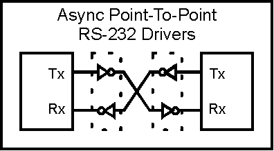
A variation of the "Point-To-Point" connection scheme uses RS-232 convertors. This is the interface method used on the IBM PC type computers. The RS-232 convertor converts the voltage levels from the TTL voltage levels to bipolar levels to be compatible with the RS-232 spec.
Blah, blah...
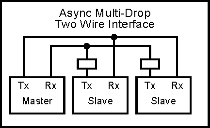
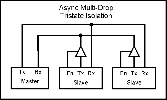
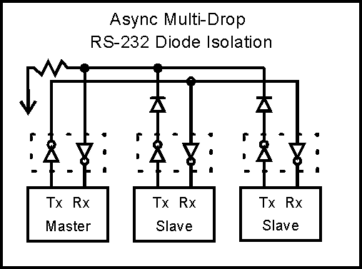
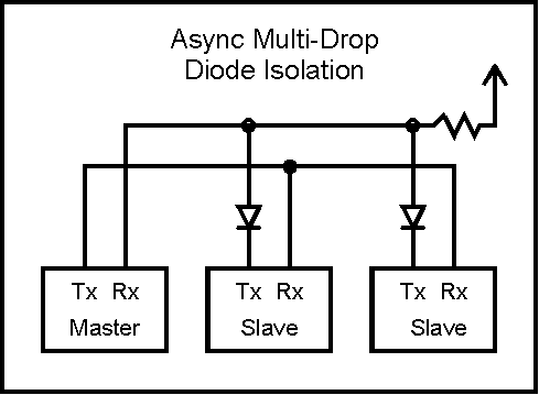
Blah, blah...
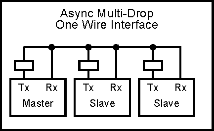
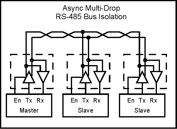
Blah, blah...
Motorola created a serial interface called SPI (Serial Peripheral Interface). This interface was created as a simplified version of the USRT. It uses a shift register to send and receive data.
Blah, blah...
Description, history, usage
References:
Previous | Index | Next
Visit Twin Cities Robotics Group
Back to my Home Page http://www.pobox.com/~jsampson
This page is currently maintained by Jeff Sampson