Simple IR proximity sensor
This page started on 01/08/01 and last updated 01/18/01
TCRG Standard Modules
Rob Turner has suggested that we define "Standard Techniques of the TCRG" for building robots. He calls these methods "Core Technologies". This is my (Jeff Sampson) first attempt at documenting such an attempt.
I picked a common device and created several methods for implementing that device. I picked the IR proxomity sensor for this example. The simplest form is an IR LED connected to a port pin of your processor and an IR receiver module. These modules have a built-in bandpass filter for noise rejection. So you have to generate an appropriate drive waveform to make the IR receiver work. The receivers I have are spec'd at 40Khz.
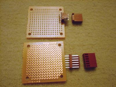
This diagram illustrates a module that could be created. I would prototype it on a Radio Shack (#276-148) perf board. This board is 1-3/4" x 1-3/4". I would use a Molex/Waldon 4-pin male connector. I would use separate wires to make a cable to connect to my main controller.
This circuit is very simple. It has the disadvantange that you have to generate the 40Khz waveform yourself. Some processors may have the ability to do this as a background task. If not, it eats into your precious CPU time.
Another approach is to add an oscillator to the IR proximity module.
Here I show an LM555 timer wired as an oscillator. It would be adjusted to the frequency that the receiver requires. The "LED" pin on the connector is an enable pin. When set to a logic high the oscillator will run and produce the 40Khz to drive the LED. When set to a logic low the oscillator will be stopped. (An invertor may be required between the 555 and the LED) So you would enable the IR proximity module and check the receiver output to see if it is active.
This diagram shows the oscillator connected to a 1 of 8 decoder, like a 74hc138. This is based on Dan Larson's NED robot. The oscillator would be active all the time. You would select a '0' on the decoder to prevent it from driving any LED. Or select '1' through '7' to enable an associated LED. You could install 1, 3, 5 or all 7 LEDs when you build the module.
I would use a 6-pin Molex/Waldom male connector for this module.
This diagram reproduces the IR proximity module as a "smart" module. This replaces the oscillator and decoder with a single chip microcontroller. Again I would use a 6-pin Molex/Waldom male connector for this module. The 4 data bits are now wired directly to the processor. So you can now program the processor to emulate the same functionality as the previuos "dumb" module. Or program 2 of the I/O bits to emulate an I2C interface. Or program 2 of the I/O bits to emulate an asynchronous serial interface. Or program all 4 of the I/O bits to emulate a bidirectional SPI interface. So you would then define commands to control the "smart" IR proximity module.
If you don't like these interface options you can define your own if you can make it work with 4 I/O bits...
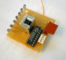
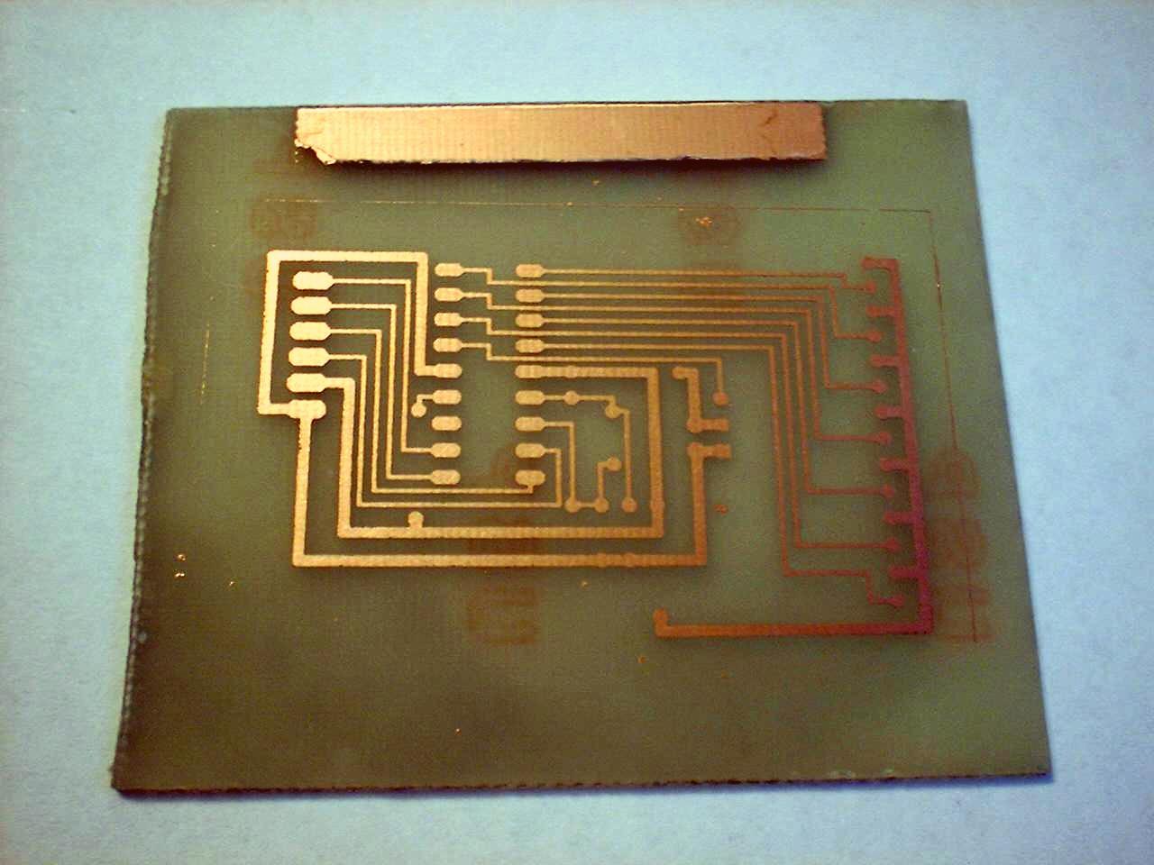
Unfortunetly I got it this far and realized the connector is on the board backwards. So I will go back and reroute it. (It is turned around now. I used one jumper because I didn't have room between the connector pads.)
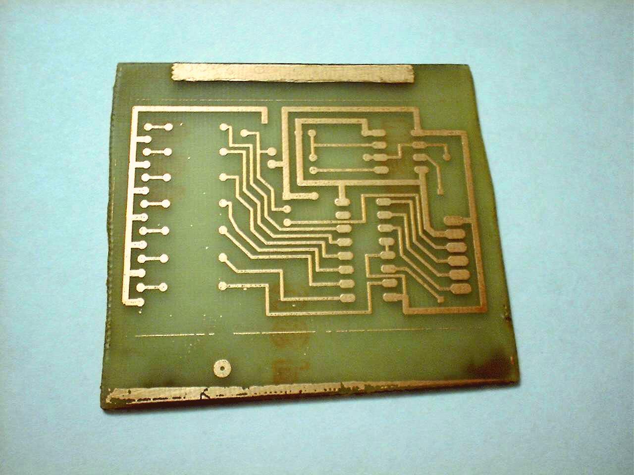
This was made with "DynaArt" toner transfer paper. I printed it from Eagle 4.0 PC board software on an HP LaserJet 4 at 600dpi. Then ironed the image onto a blank PC board. I soaked it in water to release the paper. Then etched it in ferric chloride. I had to clean the toner off the traces after it was etched.
For some reason I put the connector backwards on this one too. So I fixed it. I should have put a programming connector on this board, but I didn't.
This was made with "Press-N-Peel Blue" toner transfer paper. I printed it from Eagle 4.0 PC board software on an HP LaserJet 4 at 600dpi. Then ironed the image onto a blank PC board. Then etched it in ferric chloride. I had to clean the blue coating off the traces after it was etched.
Ideally I would define control algorithms and show sample code here. But I won't do that until people have had a chance to look at this.
Back to Index
Back to Twin Cities Robotics Group
This page is currently maintained by Jeff Sampson