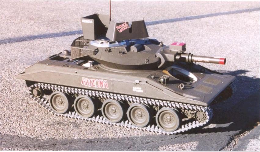
Photo 1001
|
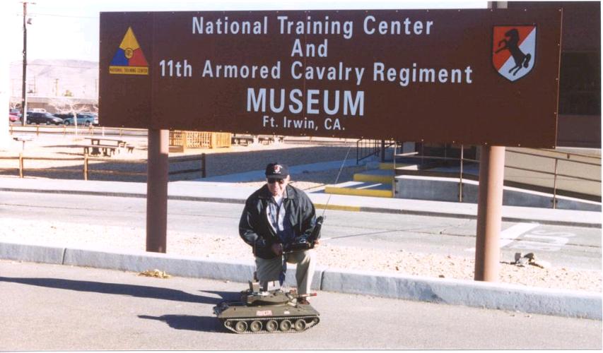
Photo 1002
|
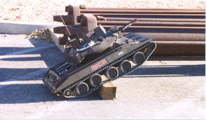
Photo 1003
|
The above pictures taken at Ft. Irwin, CA on January 21, 2002 while visiting the Museum Curator Neil Morrison.
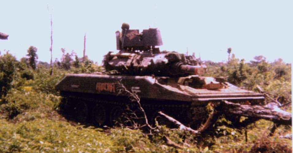
Photo 1004
|
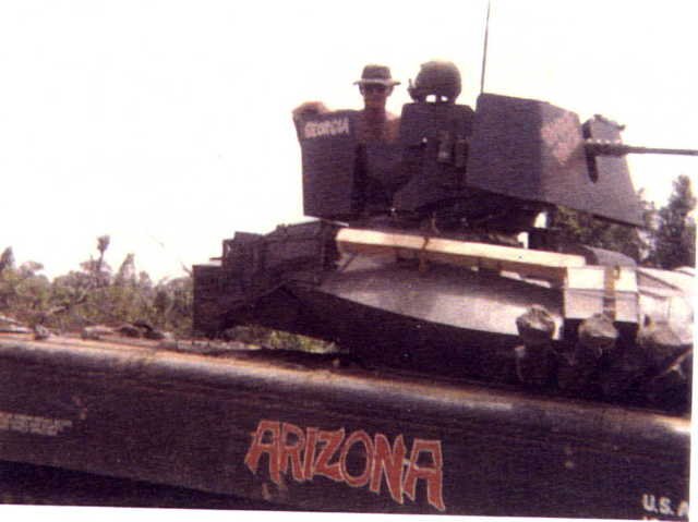
Photo 1005
|
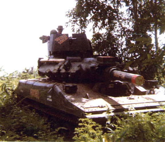
Photo 1006
|
Photos of the original 'ARIZONA' in 1970 Vietnam. Plt Sgt Ramon B. Vega, 2nd Platoon, A Troop, 11th ACR was the TC of the 'ARIZONA'.
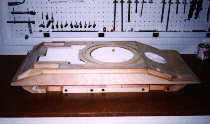
Photo 1007
|
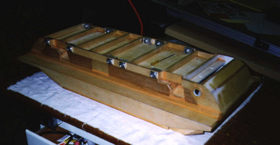
Photo 1008
|
Hull under construction. Fabricated from 1/8th and 3/16th 5 ply aircraft grade birch plywood. Fiberglass and aluminum sheet was used to reinforce all critical points.
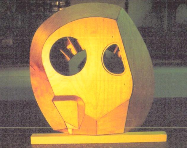
Photo 1009
|
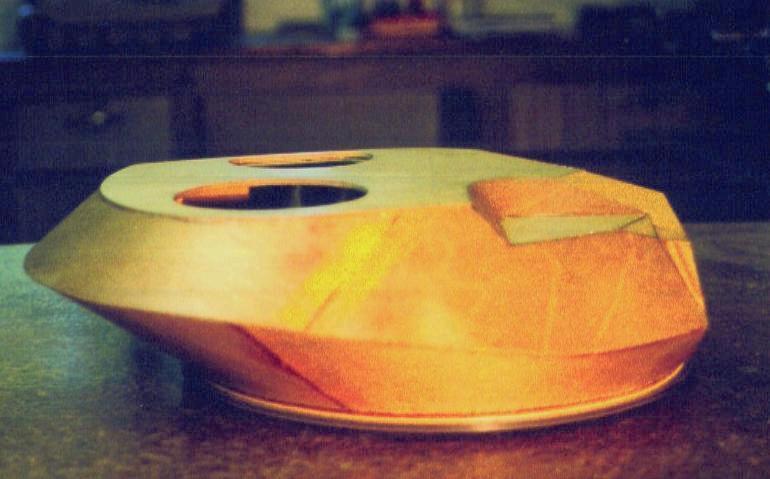
Photo 1010
|
Turret under construction. Fabricated by laminating 1/64th mahogany plywood and 1/32nd thick aircraft grade birch plywood over a skeleton of 22 shaped bulkheads of 1/8th birch plywood emanating as 15 degrees from the center.
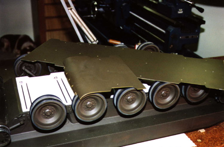
Photo 1011 Hull assembly with all suspension components in place. Torsion bars, shocks and idle wheel adjusters are fully functional. Roadwheels are supported by two ball bearings each. All parts other than the hull are machined from aluminum or steel. |
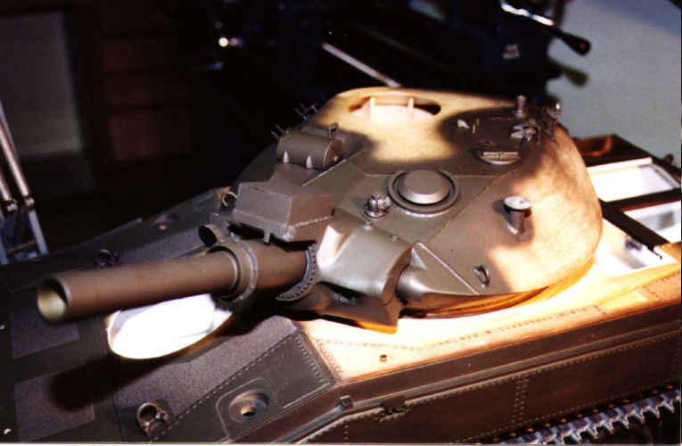
Photo 1012 Early hull and turret assembly in process. Gun barrel is machined from aluminum as is most other parts on the turret and hull. Brass is used for some parts to facilitate soldering hinges etc. |
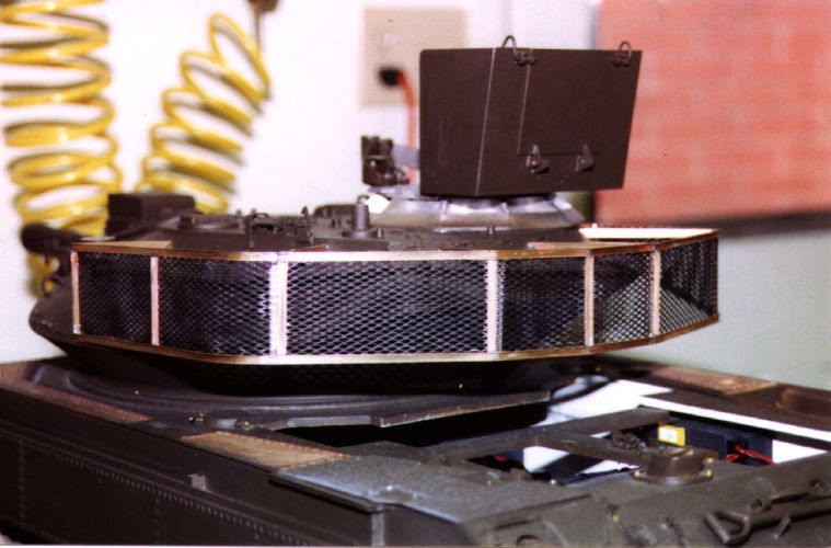
Photo 1013 The bussel rack was fabricated from brass channels and angles and steel security screen. These large bussel racks were fabrictaed 'in country' to provide the troopers with much greater storage capacity. |
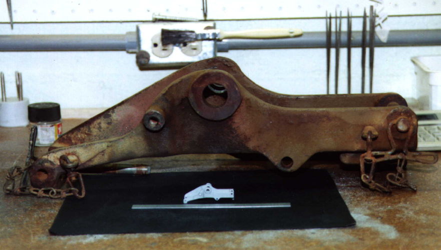
Photo 1014 The .50 cal cradle was machined from aluminum. This photo gives some idea of the size differential between full size and 1/8th size. That is a 6 inch scale in the foreground. |
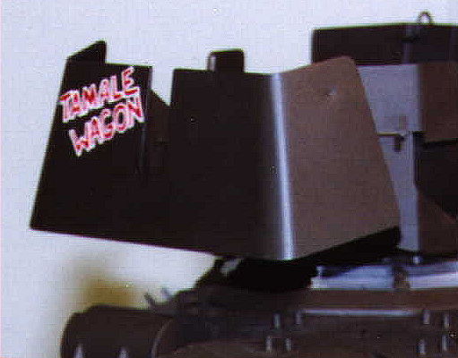
Photo 1015 The .50 cal armor shield was part of a M113 ACAV Armor Kit and was adapted 'in country' to provide some frontal protection for the Sheridan TC. |
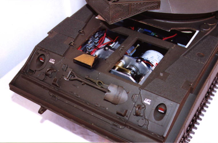
Photo 1016 The rear deck is yet to be completed. The battery cover houses the switch for the hull receiver. The air cleaner cover houses the switch and charging jacks for the main batteries. |

Photo 1017 Right side of turret showing cupola with the side and back armor. The ACAV front shield sat more vertical on the Sheridan than on the M113. |
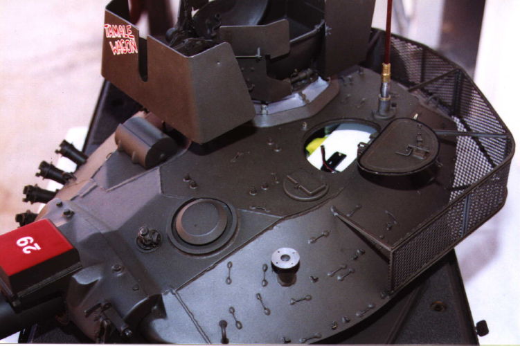
Photo 1018 Left side of the turret with loader's hatch open. In the hatch opening is the switch for the turret receiver. |
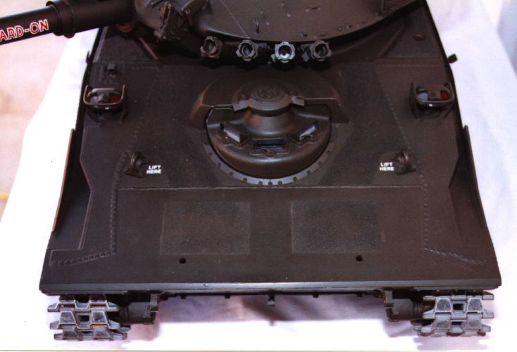
Photo 1019 The front hull deck is incomplete as the flotation surfboard is not in place nor are any of the flotation barrier covers in place around the top of the hull. |
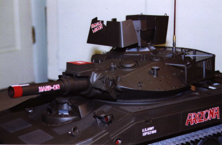
Photo 1020 The operable flotation barrier step and the fire extinquisher exterior actuating handle can be seen in this left frontal shot. |
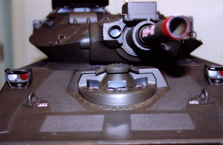
Photo 1021 All parts of the driver's hatch are machined from aluminum. The hatch rotates on ball bearings at the top. |
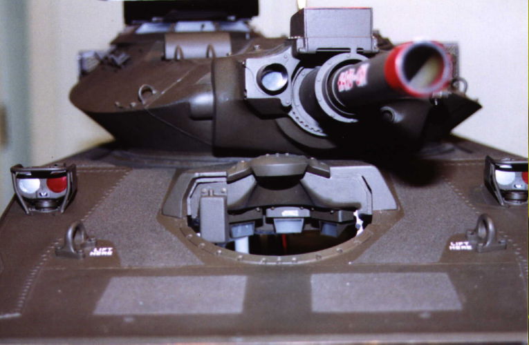
Photo 1022 Eventually there will be a driver in position. Probably a TC up in the cupola as well. |
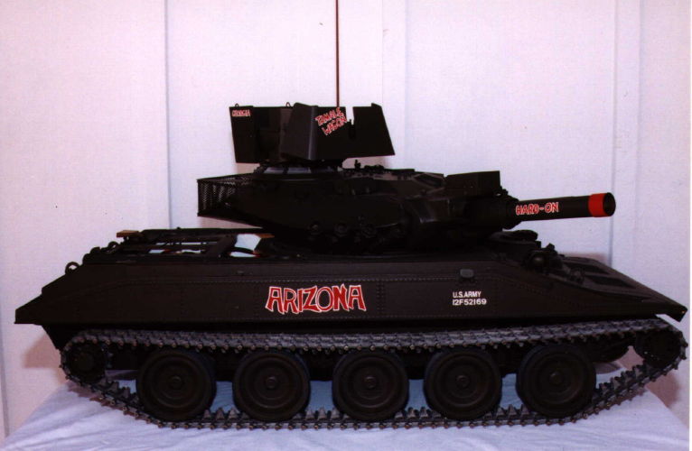
Photo 1023 The model is nearing completion, however, it will probably be the winter of 03/04 before this happens. The model was started in September 1997. Nearly 4000 hours have been expended along with many thousands of dollars for components and materials. |
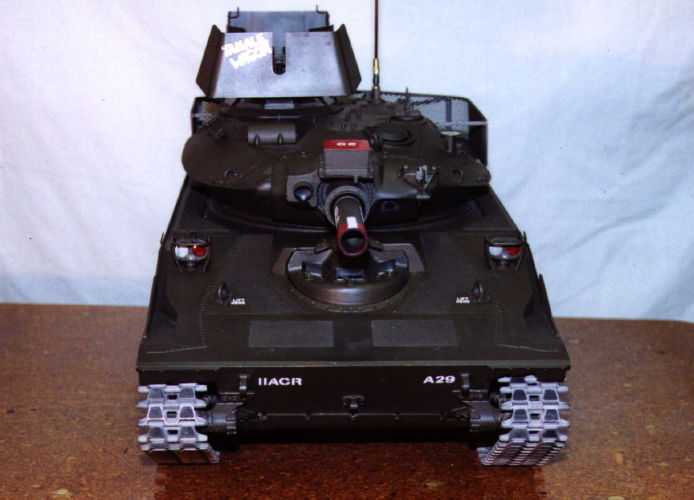
Photo 1024 The 204 track shoes are investment cast from steel and then the track pin holes reamed. Brass pins are used. The idlers and sprocket drive axles are supported by ball bearings. |
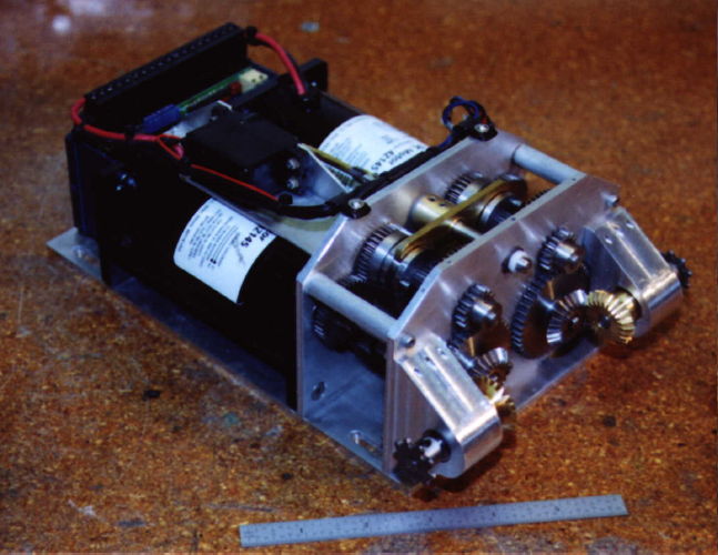
Photo 1025 The dual range drive module operates on 24 volts provided by two 7 amp hour sealed lead-acid batteries. Steering, forward/reverse and throttle are provided by a Vantec electronic controller. Shifting between ranges is by a standard servo. The final drives are two .25 roller chain. |
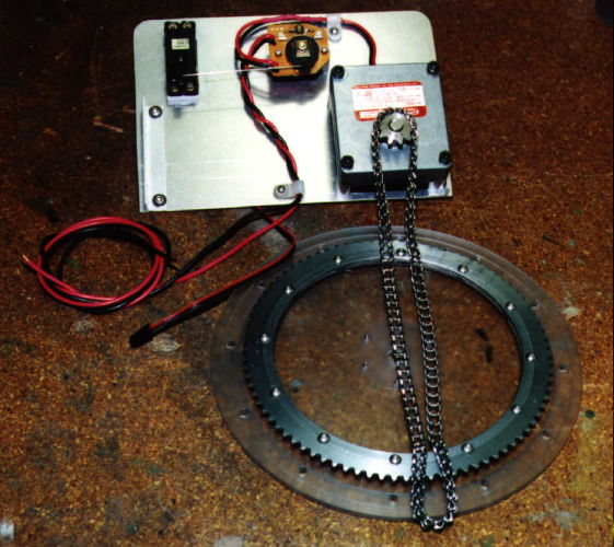
Photo 1026 A 12 volt gear motor rotates the turret using a .25 ladder chain. The driven sprocket is fastened to the lower thrust plate that sandwiches the hull flange to capture the turret. |

Photo 1027 The gun elevation is provided by a standard servo and a slotted lever. The turret has its own receiver and battery pack. Later a cupola drive and sound cards may be added. |