Introduction
[Just pictures so far...]
The heatsink
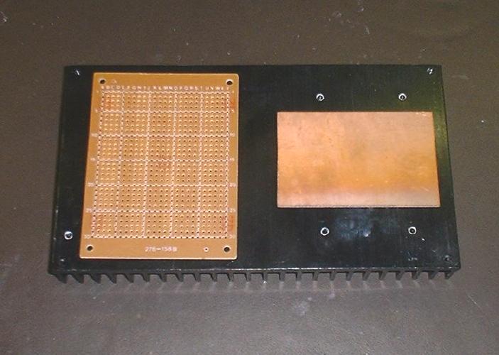
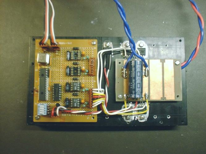
Test placement of FET board and logic board. |
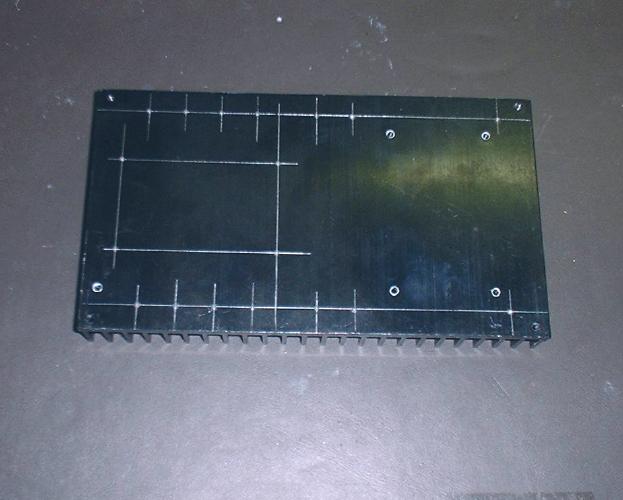
The heatsink with holes measured, scribed and center punched. |
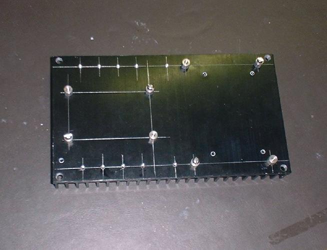
The heatsink drilled tapped and 8 standoffs installed. |
The MOSFET module
[Some elaborate description]
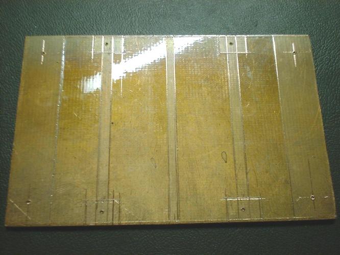
Top of FET board with packing tape. |
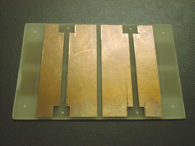
Top of FET board after etching. |
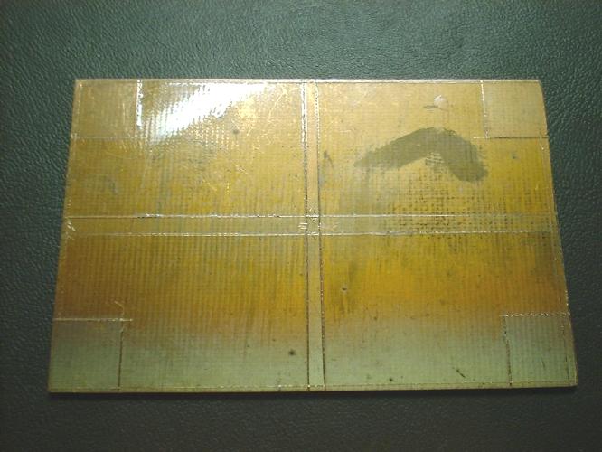
Bottom of FET board with packing tape. |
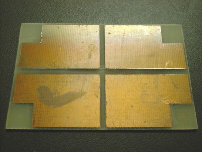
Bottom of FET board after etching. |
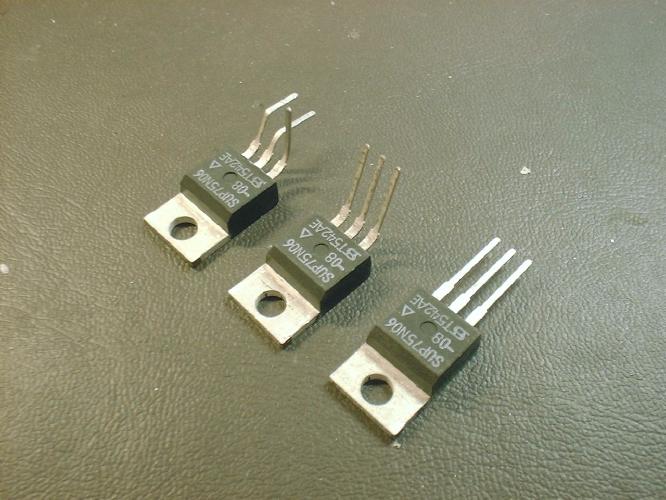
Three stages of bending the FET leads. |

Side view of a finished FET. You can see the three levels. |
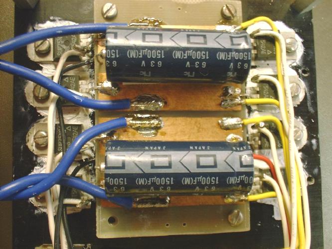
The finished MOSFET module. |
The logic module
[Some elaborate description]
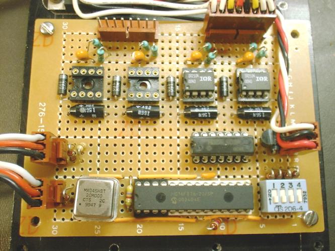
The logic module with parts for one bridge. |
Controller code
[Some elaborate description]
More pictures
The controller with parts for one bridge. |
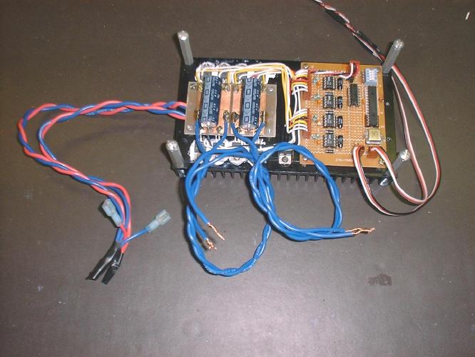
Finished controller ready for testing. |
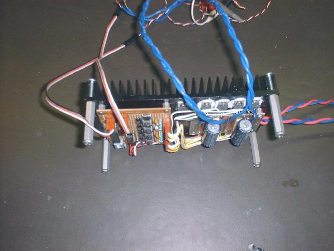
Semi-side view of controller |
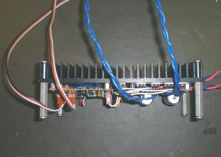
Side view of controller. |