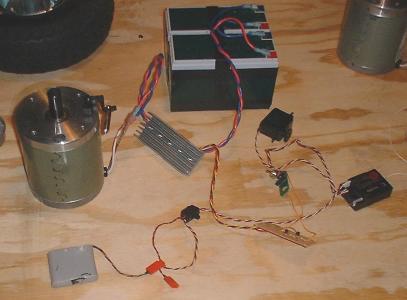
The controller connected to batteries, receiver and a motor.
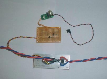
[Top to bottom]
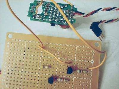
The servo board, translator board and MOSFET module.
This page created on 03/14/01 updated 03/31/01
Combat Robot Index | Home | <Prev | Next>
Motor driver - Version 1
|
The controller connected to batteries, receiver and a motor. |
[Top to bottom] The servo board, translator board and MOSFET module. |
I decided to use MOSFETs instead of bipolar transistors this time. The bipolar transistor are commonly available in 5, 10 and 20 amp devices. MOSFETS come with really big current ratings. The ones that I have, MTH40N10, are rated at 40 amps and 100 volts. You could possibly connect a logic level FET directly as is shown below.
Since a logic level MOSFET will work with a gate voltage of 5 volts, you may be able to drive it directly from the servo output. But I don't have any logic level MOSFETs so I had to make a level translator. The MTH40N10 (like most other non-logic level FETs) require around 10 to 12 volts to make them turn on hard. They also spec a max of +/-20 volts for Vgs. (Voltage from gate to source.) I had to develop a 12 volt gate drive from my 5 volt (actually 4.8v) servo signal. I used small signal bipolar transistors to do this.
As seen in the "One-FET Driver" schematic, transistor Q3 is used as an inverting switch. When +5V is applied to the input, Q3 saturates and the collector is pulled to ground potential. (actually about .2V) The resulting current pulled through R2 saturates the switch Q2. With Q2 saturated the battery voltage is supplied to the gate of the MOSFET through R3. To prevent the voltage on the gate from going above 12V I have added a 12V zener diode. The zener diode begins to conduct when the voltage is above 12V. Resistor R3 and zener D1 form a classic zener shunt regulator. Resistor R4 serves two purposes. First it is a path for the gate voltage to discharge. The other purpose is to provide a current path when the translator board is not connected. I chose to permanently mount D1 and R4 on the MOSFET. The other resistors and transistors are mounted on the perf board. So R4 provides a path to prevent static build up when the translator board is not connected. (Static will kill a MOSFET!)
The parts I had handy:
| Reference | Value | Description |
| R1 | 10K | 1/4W |
| R2 | 10K | 1/4W |
| R3 | 470 | 1/2W |
| R4 | 10K | 1/4W |
| D1 | 1NT4742A | 12V 1W Zener |
| D2 | ? | 16A ?V Fast Recovery |
| Q1 | MTH40N10 | 40A 100V MOSFET |
| Q2 | 2N3906 | Small signal transistor |
| Q3 | 2N3904 | Small signal transistor |
The good things about this driver is that is was quick and cheap.
The bad thing is that the gate is probably not being driven hard enough. (I'll know once look at it on my scope.) The problem is that the gate on a MOSFET looks like a capacitive load. My circuit has a 470 ohm series resistance for the turn on. Even worse, it has a 10K ohm series resistor for the turn off. So I am assuming it will have a noticeable turn on slope and a very bad turn off slope. Why is this important? MOSFETs are very fast devices, as long as you turn the gate on and off sharply, with nice square edges. As the slopes of the gate turn on/off become rounded, the power dissapation of the device goes up. If you try to drive MOSFETs in an h-bridge configuartion with this drive technique you will end up with two series MOSFETs turned on at the same time. This will tie your battery directly to ground through the MOSFETs. Then they will do a real good impersonation of pop corn, and blow right off the board!
But this driver does work... I'll know more after I do some testing. But it runs my 30V, 6A motors from a 24V battery on the bench.
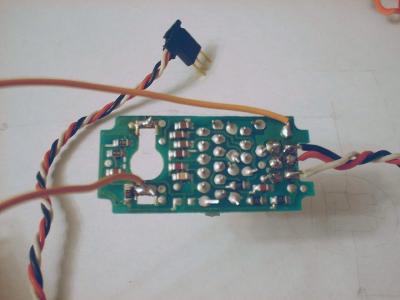
Bottom view of salvaged servo board. |

Top view of salvaged servo board. |
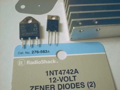
Parts for the MOSFET module. |
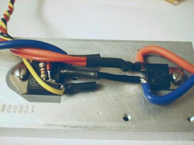
Assembled MOSFET module. |
Where to get the parts...
Combat Robot Index | Home | <Prev | Next>
Visit Twin Cities Robotics Group
This page is currently maintained by Jeff Sampson