The Yard Rover Project
Original concept
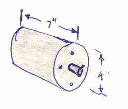
The motors are 7" long and 4" in diameter. They are rated at 25 Volts, 8 Amps, 470 RPM. So I assume that means if you put 25 volts on them they will turn at 470 RPM with no load. I also assume that if you lock the shaft and apply 25 volts, they will draw 8 amps. I didn't verify this. I figured they were big enough to do the job.
(10/7/00 Turns out this was not true. See the Earth Explorer for updated results.)
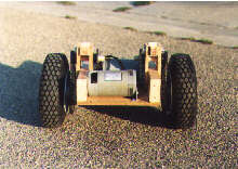
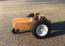
Next I needed wheels and some way to get the power from the motors to the wheels. I wanted the robot to be big enough so it could explore outside of the house. (Which seemed like a good idea anyway at the time since my motors were so big.) So with that in mind, I went down to Northern to find some wheels. Their go kart wheels looked like a good deal. They were self contained sprocket, hub, bearings, wheel and pneumatic tire. They seemed a little pricey at that point, but they sure saved alot of time. And they are great for driving through the grass.
The wheels already had a sprocket for #35 chain.
The motor shaft is 1/2" diameter.
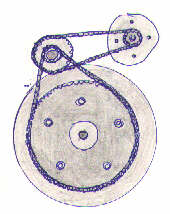
I decided I needed more reduction than I could get with a single drive.
I sat down with the motors and wheels and made a drawing.
I went down to the local hardware store and bought a 3/4" steel rod. I used 3/4" to make an intermediate shaft assembly for three reasons.
First, that was one of the sizes of bearings they sold at
Northern.
Second, I had 36 tooth #25 sprockets for that shaft size.
Third, the wheels need a 3/4" shaft anyway.
I found two 18 tooth #25 sprockets for the motor shaft.
I bought two 13 tooth #35 sprockets for the intermediate shaft.
The primary drive ratio was 36:18 and the secondary ratio was 60:13. This resulted in a overall ratio of 9.23:1. I later replaced the 13 tooth sprockets with 12 tooth sprockets to give me an overall ratio of 10:1.
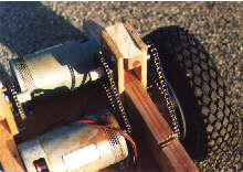
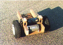
The frame is made of a sheet of 1/2" plywood which is screwed to 2x4 lumber. An axle runs across the bottom of the frame and the wheels slide onto this. The axle is secured to the bottom with conduit clamps. A 6" caster wheel is attached to the rear of the robot. The intermediate shaft support is made by sandwiching two plywood plates around the 2x4 frame member. A hole was drilled through both pieces of plywood and the bearings were pressed into the holes. A 6" length of 3/4" steel rod is slid through the bearings. The sprockets are secured to the intermediate shaft which holds it in place.
The motors are bolted to a piece of aluminum angle bracket that I had on hand. It basically just keeps the motors from turning since the weight of the motor rests against the plywood frame.
I drove it around for awhile with switches. By this time I got bored with the new robot chassis. So it was placed in the garage.
The results of the first attempt
This page is currently maintained by Jeff Sampson