Previous | Index | Next
The Earth Explorer Project
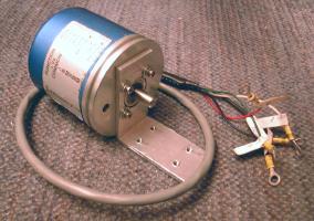
Motor requirements
"The motors are 7" long and 4" in diameter. They are rated at 25 volts, 8 amps, 470 RPM. So I assume that means if you put 25 volts on them they will turn at 470 RPM with no load. I also assume that if you lock the shaft and apply 25 volts, they will draw 8 amps. I didn't verify this. I figured they were big enough to do the job."
I don't think this assumption was correct. We did some quick experiments the first day I had the Earth Explorer at Alan's house. One experiment was to measure the stall current of the motors. We used the two car batteries in series for a supply. We had Alan's DVM connected to measure current. Brynn wedged his foot between the tires to lock one of the motors. We connected the power and the 10 amp meter pegged out. Hmm...
I was predicting it would be 8 amps. Since it was over 10 amps I have to concede that I was wrong. :-) So it must be that the numbers of 8A and 470RPM are for a "loaded" condition. But they don't list what constitutes a loaded condition. If it said 1/3HP, then it would make sense that it turns at 470RPM and draws 8A when generating 1/3HP. But they don't list horse power. So I will have to measure the actual stall current.
The easiest way I can think of to measure stall current is to lock the armature and apply power. (Which I guess is the definition.) It should be fairly easy to lock the armature with the motors bolted down. I just need to clamp a pair of Vise Grips on the motor shaft and let it rest against the floor of the box. I just have to make sure I know which direction it is going to turn. If I get it wrong it will swing around and whack the box on the other side. Possibly doing some real damage.
So I did the Vise Grip experiment. I had to be able to measure more than 10 amps so I used one of my 50 amp shunts. I measured it's voltage drop with my Fluke meter. The motors draw approximately 20 amps when in a stall condition.
Note: I ended up using my 10 amp analog meter and a 6V battery. Since I am measuring the resistive component I decided to use a lower voltage battery. Then I just multiplied the reading by 4.
Actually, the worst case current draw would be trying to reverse a motor that is turning at full speed. Because the motor is generating a back EMF which is approximately equal to the applied voltage. So when you apply full voltage in the reverse direction you will have the supply voltage + the back EMF voltage. And twice the voltage results in twice the current.
This condition doesn't last for long. But the drivers need to be able to handle the current.
Driving the motors
I ran across the Open Source Motor Controller project on the web. It was designed for a Robot War type of machine. His design goal was to have a controller that would provide up to 100 amps. I don't need that much current but I liked the MOSFET driver he was using. I got the spec sheets for the Harris HIP4081A driver.
I plan to start with the schematic from the eval board. I will use 4 MTH40N10 MOSFETs because I already have them. These are rated at 40 amps continuous and 100V gate-drain. B.G. Micro had a good deal on them. They were either $0.39 or $0.49 each. The drawbacks are that they are in a TO-218 package instead of a TO-220 and they were removed from boards. So they are a little hacked up. I think I got the HIP4081A from Allied Electronics. But you can find them at FindChips.
I found some cute little heatsinks at ABC Electronics. They are approximately 4"L x 1-1/2"W x 3/4"H and are predrilled for 5 TO-220 parts. The TO-218 fits the same holes even though they are larger. I was quite surprised when I went to buy the Sil-Pads to mount the MOSFETs. Turns out they were going to run me around $0.85 each, or almost twice the cost of the MOSFET itself. So I scrounged around at ABC Electronics and found TO-3 Sil-Pads for $0.05 each. They can be cut down to fit. If I were to go with separate heatsinks for each FET I wouldn't have to isolate them. If I were going to parallel FETs I would do this.
Originally I was going to wire a motor controller on perf board. I was going to use 12 gauge house wire for the high current section. But after seeing the results that Ron and Brynn are having with an HP plotter and a Sharpie marker, I have decided to make a PC board.
I will probably use a screw terminal block for the main power and motor connections. The control connector will probably be the 0.1" Molex connectors.
Motor PID control
Quadrature encoder
This encoder will be connected directly to the end of the motor shaft. I found an adapter that was threaded to screw onto a 1/2" bolt. It had a 1/4" hex hole punched in the end. I had Alan cut the threads out with his lathe so it slipped on the motor shaft. I inserted a hex stand-off into the hex hole. I cut a piece of rubber hose to couple the hex stand-off to the encoder shaft. The encoders are then bolted down to the wooden base.
The encoder will be used with PIC_SERVOs.

Dual PIC-SERVO prototype
This is the PIC-SERVO prototype that I built for the Research 2 robot. It has two PIC-SERVO channels and an RS-232 convertor. I plan to layout a PC board for this. This controller will connect to the quadrature encoders and to the motor driver boards. It will communicate with a processor over a serial interface.
Visit Twin Cities Robotics Group
Back to my Home Page http://www.pobox.com/~jsampson
This page is currently maintained by Jeff Sampson