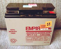
I found these batteries at Northern's clearance store.
This page started on 10/8/00 and last updated 11/19/00
Previous | Index | Next
The Earth Explorer Project
As your batteries get bigger you need to start thinking about fuses. Even small ni-cads pack enough energy and a low internal resistance. They will burn you if you short them. My batteries are going to be 17AHr flooded lead acid batteries. I was curious how much current I could get out of these in case I made a Battle Bots type machine. I asked Alan if he knew and he looked in his "battery bible". He found that a lead acid battery will put out a current of 10C. "C" is the amp hour rating of the battery. So 10 x 17 = 170 amps! There was also a graph that said the battery can put out this kind of current for about 2 minutes. Now that could do some REAL damage. So I would be wise to fuse these babies...
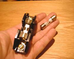
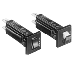
These fuses are rated at 35 amps at 32 volts. The voltage is within my range since I am running a 24 volt system. Actually the battery voltage will probably reach 30 to 32 volts in normal operation, but that is what the fuses are rated for. So you are probably wondering why I picked 35 amp fuses... I was expecting the motors to draw around 15 amps each in a stall condition. So I figured 2 x 15 = 30 amps and I still had a couple to spare.
I went back and actually checked my stall current. It is more like 20 amps. And 2 x 20 = 40 amps. So the 35 amp fuses aren't going to cut it. Unless I want to blow a fuse when the motors stall. Actually I need to be able to supply full stall current to get max power from the motors. Otherwise I may have to walk a mile or two to get it unstuck. Or replace the fuses!
The fuses really should be used as a short circuit protection rather than a max current control. It is better to limit your current electronically if you want it limited. I don't expect a fuse to protect the motors. It is more likely that the motor controller will short out. And I just want to keep the flames to a minimum!
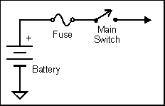
So as Bryan suggested, I should fuse each motor separately and also have a main fuse on the battery. He also suggested a dual circuit breaker for the motors. That way when one trips it will shut off the other one at the same time. I'll have to look into that.
I think ABC also had 40 and 50 amp fuses to fit the same holder. So I will probably get a 50 amp fuse for the main fuse.
The electronics section will have an appropriately sized fuse. Probably around 5 amps. I also have to decide if I want to be able to switch the motor power and electroincs power separately.
That leaves me with finding a rather large power switch that is rated at least 50 amps. Or I could use a small switch and use a power contactor (a big relay) to control the main power. So I will have to scrounge around and see what I can find. A power contactor would be better because I can control it from my stop switch.
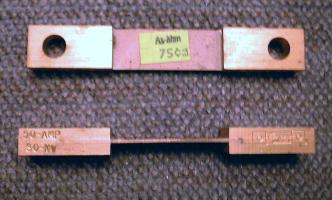
I plan to put a 50 amp shunt in series with the battery to measure current in and out of the battery. By integrating instantaneous current readings I should be able to calculate the amp/hr usage of the battery. That way I can predict when the battery will be getting low. This reading will also be passed to the alternator unit to control charge current for the battery.
I can use A/D convertors to measure voltages at various points in the power system. I can also use the A/Ds to measure temperatures. Like the motor controller temp, motor temp, DC/DC convertor temp, etc.
Once I get my machine to move under it's own power I can add some more goodies to the power system. Things like voltage, current and temperature monitoring. The addition of the engine/alternator will add to the complexity of the power system. But most of it's control will be self-contained.
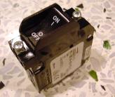
The large and small breakers
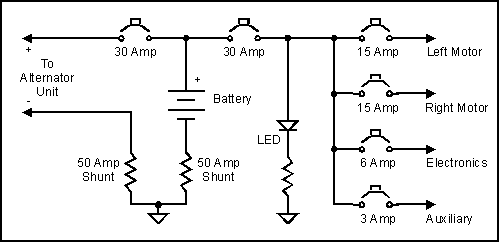
Diagram of the power center done with Corel Draw
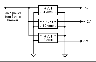
Diagram of the DC/DC convertors
The two DC/DC convertors on the prefabricated module have some extra diodes and fuses on the back side. It also has an electrolytic capacitor on the input. These are not shown in the diagram. The smaller convertor (5V @ 2A) has its output wired backwards to create a negative supply.
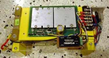
DC/DC convertors mounted to front of a battery box.
The battery shunt is visible on the left side.
The breakers are on the right side of the box.
 |
 |
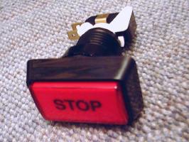
| Lighted "Stop" switch. It has a 12V bulb and a microswitch. |
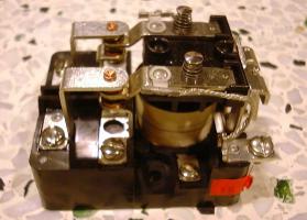
Power contactor |
I may as well use my industrial "relay logic" experience that I picked up working at PAR Systems. I can have one pushbutton latch a relay and energize the main power contactor. When the stop pushbutton is pressed the relay will drop out and deenergize the power contactor. So this can be done independently of electronics or software. So that is one less high-tech thing to worry about.
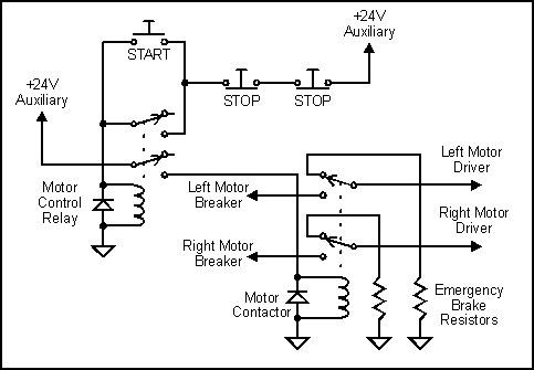
Diagram of motor power relays
Visit Twin Cities Robotics Group
Back to my Home Page http://www.pobox.com/~jsampson
This page is currently maintained by Jeff Sampson