
Finally found my hdmi adapter, got the Rpi running with Bluetooth mouse and keyboard. I’ve downloaded NoMachine to my iPad and Rpi5.
So now I think I’m getting confused which machine is server and which is/are clients on their NoMachine Network. I also want to add my Ubuntu laptop. oh hell why not add my iPhone to the chaos as well!
I would like to see/ control the Rpi on my iPad and or Ubuntu laptop. OR phone.
Any advise?


Assume your RPi is the server and all other machines are clients accessing the server/RPi.
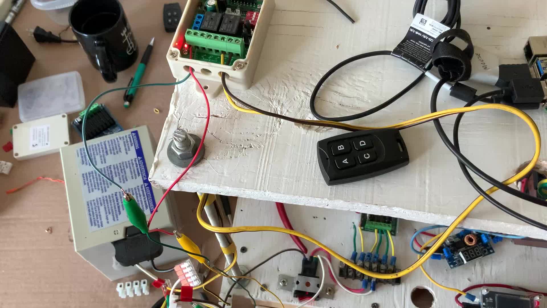
I'm soldering up my radio control PCB board. The first issue is I need a more permanent solution for mounting my batteries than rubber bands. The second issue is all my LED were solid blue. Seems instead running the level shifter 1OE to GND I ran it to 5V. Why on earth did I do that? Now I'll be slicing and re-wiring. 😞


I think I have recovered from my wiring screw up and can individually address my 4 LEDs on my radio control board.


Info from today's video meeting.
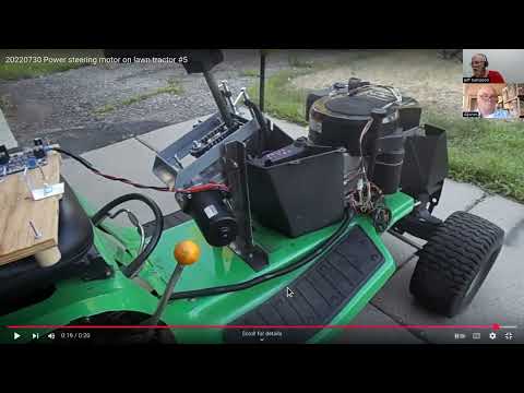
====== 20250529 ROS Lawn Tractor Automation meeting - Length 48:56 This video: https://youtu.be/bGporaP7cOw
Chat/Notes: Al's Miro board: https://miro.com/app/board/uXjVM1yzdFo=/ Al's github: https://github.com/jones2126/ Al's Jupyter Notebook directory. https://github.com/jones2126/ros1_lawn_tractor_ws/tree/master/project_notes/jupyter_notebooks Al's gist channel: https://gist.github.com/jones2126
Remote access GUI software: https://www.nomachine.com/
Index: 00:00 Jeff: Says he is mostly caught up on Internet maintenance. A Slack problem and how he fixed it. Proposed enhancements for common link section. 08:05 Jeff: Explanation of the links at the bottom. 12:45 Jeff: Fighting with Slack to stay current. 16:50 Jeff: Thinks about documentation techniques. (Apparently the screen sharing should have been turned off...) 18:10 Screen sharing gets turned off and a notebook is manually shown. 20:35 Bob: Wants to use "NoMachine" (like RealVNC) to get remote access. 23:35 Bob: Describes his RPi5 hardware setup. 24:30 Bob: Stories about his new house. 24:45 Jeff: Asks about the Blue Tooth keyboard connection. 31:15 Bob: Shows us his small on-screen keyboard. 32:20 Bob: Attempts to log-in with nomachine. 35:15 Al: Is going to run through the steps to start nomachine. 45:15 Al: Is assembling his remote control board. Also shows the lawn tractor end.
==
Link to access the Slack channel: https://tractorautomation.slack.com/
Lawn Tractor Automation YouTube page: https://www.youtube.com/@lawntractorautomation2726/videos
Index for Lawn Tractor Automation Zoom meetings: http://sampson-jeff.com/RosAgriculture/LawnTractorMeetingNotes.htm http://sampson-jeff.com/RosAgriculture/LawnTractorMeetingNotes.txt
Index for the original ROS Agriculture Zoom meetings (~250 videos): http://sampson-jeff.com/RosAgriculture/readme.txt (Use following link, or newest file in that directory) http://sampson-jeff.com/RosAgriculture/ros-agriculture-youtube20230104.txt

I downloaded 56 files from Slack referenced in this .html file. http://sampson-jeff.com/RosAgriculture/slack_exports/20241211-20250306/Slack%20Export%20-%20%23random.html
I uploaded them to Google here: https://drive.google.com/drive/folders/1jz24vf-OPXxCAP16JOrDLshshGm_NwTk?usp=drive_link
I'm just guessing at this point, but I think the .html file would have to be updated to reference sampson-jeff.com instead of files.slack.com
<a href="<https://files.slack.com/files-pri/T8WP3RHH7-F084P6EBZQF/pxl_20241214_010508824.jpg?t=xoxe-302785867585-8559250340533-8558319062245-a691cf9719c6c1b2b920370623f579a8>">PXL_20241214_010508824.jpg</a>
@Al Jones You're a genius!
It did not occur to me to include the channel name and the mystery ID into the file name. That solves numerous problems down the line.
And you obviously have some really juicy Python tools in your bag of tricks.
I ran your Python code against all 3 backups that have been published. (I still need to publish the last backup.) But, I have the "original" files/images backed up so hopefully we won't lose them.
The original backup with about 2 years of history yielded 12 images, that I did not expect to be there, since they are 2 to 3 years old
So yes, I need to figure out how to modify the the HTML code to point to the new images/files that I just downloaded. But obviously I will have to consult with Al to get that to work.... 🙂
The backups (that have not been fixed yet): http://sampson-jeff.com/RosAgriculture/slack_exports/
*Thread Reply:* Did you use my cached credentials? If so, I'm surprised they still worked. I put the 5 second delay in to try and protect from being banned if slack decided the download was dubious.
*Thread Reply:* I did not know anything about credentials, I just ran it. It worked on the back-up chunk you listed (with a 5 second delay). But the first back-up chunk said it found 476 (or so entries) so I reduced the value from 5 seconds to 1 second. Everything worked. More mysteries?
*Thread Reply:* At some point the download will likely fail and this code will have to be updated.
*Thread Reply:* Oh. that is what that mess is. The original links had something similar, but I had no idea what it was.
I’ve had a frustrating experience trying to find my ip address on our home router…UNTIL..I found software called “Angry IP Scanner”. I found everything including tv, smart appliances etc.
*Thread Reply:* I can control my laptop with my iPad! I am a happy camper!
I see they have upgraded Ubuntu from 24.04. Anyone having troubles with the newer Ubuntu 25.
*Thread Reply:* I have not used it since ROS support is not available yet.
Well, keep in mind the versions of Ubuntu (and other things) aren't exactly normal. I think the next LTS "Long Term Support" version of Ubuntu will be 26.04. Here go read this for background: https://ubuntu.com/about/release-cycle I was wrong. 25.04 LTS is the next LTS version which was released in April.
I think I am running 20.04.

@Jeffs thanks for the link! I’m at 24.04.2 right now. I’d rather not bang my head on the bleeding edge of progress! So I’ll stay where I’m at.

Making a little progress on my radio control device using Teensy 3.2 and NRF24 radio. Radio Control code link Tractor Teensy 3.5 code link
Both are shell programs to test using the programmable LEDs for displaying status and confirming the mode switch is working to detect 3 different operating modes. The other key test is to track the Hz of radio communication. Given I have a green led in the top left, that shows my radios are operating > 5 Hz.
The output from the 'tractor' Teensy 3.5 shows my radio rate at 10 Hz.
Received packet, size: 24
Data: steering=9999.00, throttle=0.00, mode=1, counter=70
Received packet, size: 24
Data: steering=9999.00, throttle=0.00, mode=1, counter=71
Current communication rate: 10.00 Hz
Received packet, size: 24
Data: steering=9999.00, throttle=0.00, mode=1, counter=72
Received packet, size: 24
Data: steering=9999.00, throttle=0.00, mode=1, counter=73
Received packet, size: 24
Data: steering=9999.00, throttle=0.00, mode=1, counter=74
Received packet, size: 24
Data: steering=9999.00, throttle=0.00, mode=1, counter=75
Received packet, size: 24
Data: steering=9999.00, throttle=0.00, mode=1, counter=76
Current communication rate: 10.00 Hz


Trying to get this data structure to work, sending and receiving between my radio control unit and the Teensy 3.5 on the tractor. For some reason the data is not passing correctly.... yet 😞
struct RadioControlStruct {
    float steering_val;     // 4 bytes - Pin 15
    float throttle_val;     // 4 bytes - Pin 14
    float voltage;          // 4 bytes - TBD
    float pot3_val;         // 4 bytes - Pin 16
    float pot4_val;         // 4 bytes - Pin 17
    byte estop;             // 1 byte - Pin 10
    byte control_mode;      // 1 byte - Pins 3 and 4
    byte button01;          // 1 byte - Pin 9
    byte button02;          // 1 byte - Pin 6
}; // Total: 24 bytes
More details on what @Bob Hassett found, https://www.ivtinternational.com/news/agriculture/autonomous-agxeed-agbot-5-115t2-sets-new-world-ploughing-record.html
Got my NRF24 to NRF24 radio issue working. Now passing all data from my radio control unit to the 'tractor' Teensy 3.5. I have 4 potentiometers, three pushbuttons and a toggle switch for mode.
Current communication rate: 10.00 Hz
Data: steering=-0.00, throttle=0.08, pot3=0.01, pot4=-0.08, voltage=7.3V, estop=0, mode=0, btn01=0, btn02=0
Data: steering=0.06, throttle=0.11, pot3=0.07, pot4=-0.07, voltage=7.3V, estop=0, mode=0, btn01=0, btn02=0
Data: steering=0.06, throttle=0.04, pot3=0.09, pot4=-0.08, voltage=8.1V, estop=0, mode=0, btn01=0, btn02=0
Data: steering=0.08, throttle=0.08, pot3=0.07, pot4=-0.07, voltage=7.6V, estop=0, mode=0, btn01=0, btn02=0
Data: steering=0.06, throttle=0.09, pot3=0.07, pot4=-0.08, voltage=7.5V, estop=0, mode=0, btn01=0, btn02=0
Radio control, transmitter, Teensy 3.2 code link
Tractor, receiver, Teensy 3.5 code link
Attached image of data structure code for radio 24 byte data packet:


Info from today's video meeting.
====== 20250605 ROS Lawn Tractor Automation meeting - Length 43:17 This video: https://youtu.be/WJ2Cj6Cbek8
Chat/Notes: Al's Miro board: https://miro.com/app/board/uXjVM1yzdFo=/ Al's github: https://github.com/jones2126/ Al's Jupyter Notebook directory. https://github.com/jones2126/ros1_lawn_tractor_ws/tree/master/project_notes/jupyter_notebooks Al's gist channel: https://gist.github.com/jones2126
Home Brew Robotics Club links: https://www.hbrobotics.org/ https://www.youtube.com/user/hbrobotics/featured https://www.hbrobotics.org/index.php/meeting-archive/ https://www.youtube.com/watch?v=2SdPiJxo5wg AI pair programming in your terminal https://aider.chat Dallas Personal Robotics Group links: https://www.dprg.org/ https://www.youtube.com/@DPRGclips/videos Index entry for problem of which board, which OS version, which ROS version: http://sampson-jeff.com/RosAgriculture/LawnTractorMeetingNotes.htm#20250206
Index: 00:00 Jeff: Mention of the video index (chapters) and links below this video. 01:00 Jeff: Some thoughts on our Slack back-up attempts. 03:25 Jeff: Fixing the delinquent meeting descriptions on Slack. 07:55 Al: Asks about merging the multiple Slack back-ups into a single file. (No, not easily.) And some extra discussion on the old ROS Agriculture videos and my index for those. 15:00 Jeff: Talks about the latest Home Brew Robotics Club meeting video. 17:50 A short look at Dallas Personal Robotics Group. 19:35 Jeff: Goes over the problem of which board, which OS version, which ROS version. 22:40 Jeff: Update on organization after moving. 26:10 Jeff: Summary of recent accomplishments. 26:40 Jeff: Parts lost in the move. And alternatives. 30:10 Al: Shows his new remote control system. 34:45 Jeff: Asks why the remote control would not originally communicate. 37:20 Al: Quick show-and-tell of the remote control. 38:20 Discussion of batteries. 42:20 Quick indication of signal quality.
==
Link to access the Slack channel: https://tractorautomation.slack.com/
Lawn Tractor Automation YouTube page: https://www.youtube.com/@lawntractorautomation2726/videos
Index for Lawn Tractor Automation Zoom meetings: http://sampson-jeff.com/RosAgriculture/LawnTractorMeetingNotes.htm http://sampson-jeff.com/RosAgriculture/LawnTractorMeetingNotes.txt
Index for the original ROS Agriculture Zoom meetings (~250 videos): http://sampson-jeff.com/RosAgriculture/readme.txt (Use following link, or newest file in that directory) http://sampson-jeff.com/RosAgriculture/ros-agriculture-youtube20230104.txt
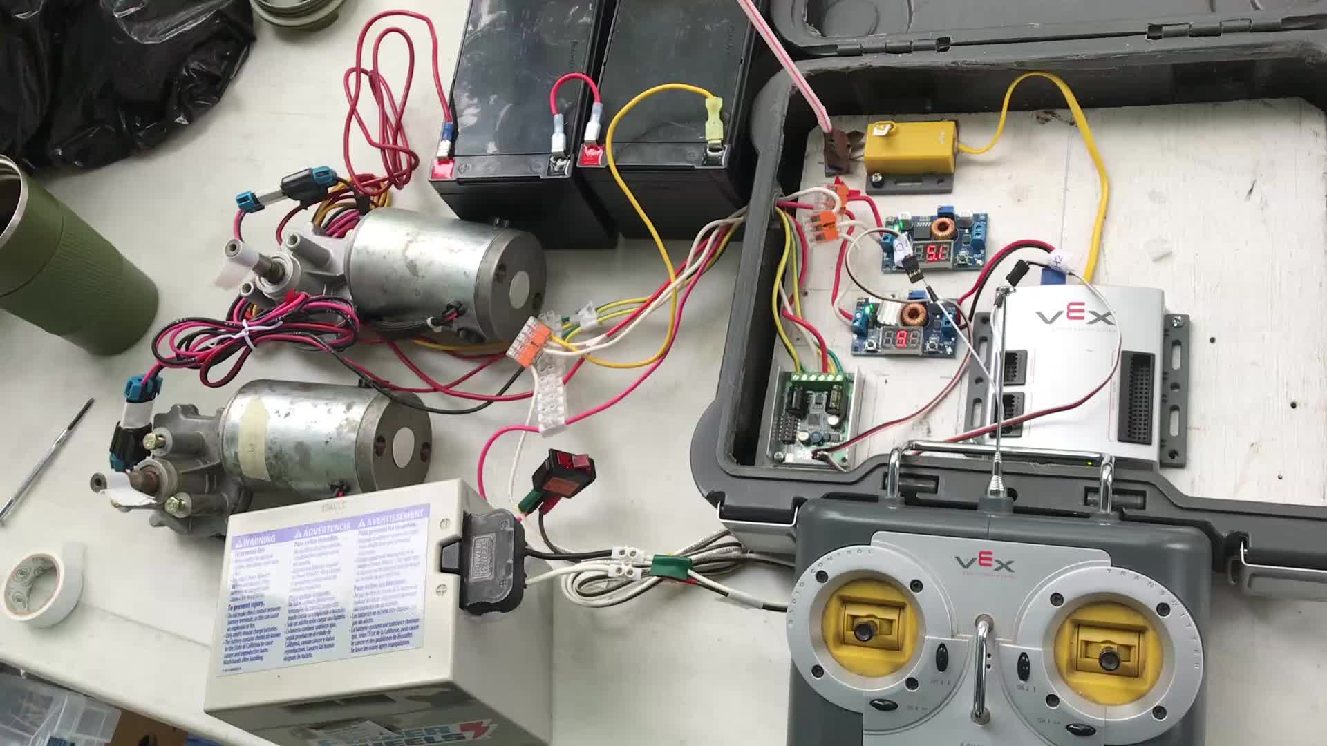
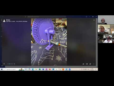
I wired up my molex connection for my linear actuator and 3D printed a holder for the connector. Now I need to get code updated to move the actuator based on my radio control.


This is what I was trying to explain during the zoom meeting. My “Remote controlled stop circuit.” I’ll add pictures at a later date.

@Bob Hassett What is the part number of your original motor driver board? And did you plug that directly into your Vex controller?
Here is the quick start guide for the Sabertooth 2x12 https://cdn.robotshop.com/media/D/Dim/RB-Dim-43/pdf/sabertooth-dual
VEX motors run on 7.2 v
So how much control voltage can the Sawtooth take? Will that VEX 3 wire 7.2 output burn out the Sawtooth 3 wire input control?
I’ll dig around and find some small motors to hook up and try mating up the 3 wire connections from the vex to the sawtooth? Can’t do it tonight. Will try it tomorrow night. Btw current toggle settings are 1down 2up 3up 4down 5down 6down
*Thread Reply:* I tested the old setup with the sawtooth. No matter what I tried it seems as though there is an internal After reading more. The VEX does put out an RC modulation.
I tried the old sawtooth motor controller….long story short it seems there is an internal short. One motor turns all the time with out the vex signal connected. Isolating and testing each channel same results… motor runs continuously.
So…. first I’ll install my new remote controlled stop circuit. Then I’ll install the new controller but after I read more about its configuration.
Info from this week's video meeting.
====== 20250612 ROS Lawn Tractor Automation meeting - Length 30:01 This video: https://youtu.be/uUaP8xhvnZY
Chat/Notes: Al's Miro board: https://miro.com/app/board/uXjVM1yzdFo=/ Al's github: https://github.com/jones2126/ Al's Jupyter Notebook directory. https://github.com/jones2126/ros1_lawn_tractor_ws/tree/master/project_notes/jupyter_notebooks Al's gist channel: https://gist.github.com/jones2126
HBRC thread about abandoning Micro ROS: https://groups.google.com/g/hbrobotics/c/F5V5r3wdyU0 Michael's main github page: https://github.com/wimblerobotics/Sigyn/tree/main The significant parts to replace Micro ROS: https://github.com/wimblerobotics/Sigyn/tree/main/sigyn_to_teensy https://github.com/wimblerobotics/Sigyn/tree/main/teensy_to_sigyn And dig through the github for launch files and maybe configuration... A newer thread about this: https://groups.google.com/g/hbrobotics/c/9nPrywR6Jqg (Or better yet, subscribe to this Google group as a digest. Then you can keep up to date on what people are doing.)
Al: Github for embedded code that will run on my autonomous lawn tractor: https://github.com/jones2126/tractor2025
Index: 00:00 Jeff: Mention of the video index (chapters) and links below this video. 00:35 Jeff: Raspberry Pi 4, random comments. 01:30 Jeff: The "lost" Raspberry Pis. My original Raspberry Pi robot. (RPi2) 03:30 Jeff: HBRC thread about abandoning Micro ROS. 05:50 Jeff: What I need to do to get my robot publishing again. 08:50 Jeff: Raspberry Pis are still lost... 09:10 Al: Dug through Michael Wimbal's github while Jeff was talking. 10:55 Al: Talks about his linear actuator. 13:45 Al: Talks about his radio control. 17:40 Bob: Talks about his Raspberry Pi 5. He has a new remote control receiver. A new motor driver board. 23:10 Al: Use case; Harassing varmints. 26:00 Jeff: Talks about Bob's new motor driver board.
==
Link to access the Slack channel: https://tractorautomation.slack.com/
Lawn Tractor Automation YouTube page: https://www.youtube.com/@lawntractorautomation2726/videos
Index for Lawn Tractor Automation Zoom meetings: http://sampson-jeff.com/RosAgriculture/LawnTractorMeetingNotes.htm http://sampson-jeff.com/RosAgriculture/LawnTractorMeetingNotes.txt
Index for the original ROS Agriculture Zoom meetings (~250 videos): http://sampson-jeff.com/RosAgriculture/readme.txt (Use following link, or newest file in that directory) http://sampson-jeff.com/RosAgriculture/ros-agriculture-youtube20230104.txt

Trying to get full control of the motion of my JRK G2 actuator motor controller. What they call the 'compact' protocol seems to be working.
void setJrkTarget(uint16_t target) {
    if (target > 4095) target = 4095;  // Safety limit
    Serial3.write(0xC0 + (target & 0x1F));
    Serial3.write((target >> 5) & 0x7F);
}
The more 'robust' protocol I could not get to work.
void setTarget(uint16_t target) {
  // Pololu Protocol: 0xAA, device #, command, low byte, high byte
  const uint8_t deviceNumber = 11;  // Default JRK device number
  Serial3.write(0xAA);              // Command header
  Serial3.write(deviceNumber);
  Serial3.write(0x40);              // Command: Set Target
  Serial3.write(target & 0x1F);     // 5 low bits
  Serial3.write((target >> 5) & 0x7F); // 7 high bits
}
Once I was able to get the actuator to fully move, I had the issue of the potentiometer on the radio control is a bit noisy. So I tried a couple of different approaches to smoothing out the jerk in the actuator. One was to 'bucket' the values and corresponding JRK target.
const uint16_t bucketTargets[10] = {
    3696,  // Bucket 0: transmission_val ~1023 -> full forward
    3358,  // Bucket 1: transmission_val ~920
    3020,  // Bucket 2: transmission_val ~818
    2682,  // Bucket 3: transmission_val ~716
    2344,  // Bucket 4: transmission_val ~614
    2048,  // Bucket 5: transmission_val ~512 -> neutral
    1710,  // Bucket 6: transmission_val ~410
    1372,  // Bucket 7: transmission_val ~307
    1034,  // Bucket 8: transmission_val ~205
    312    // Bucket 9: transmission_val ~102-1 -> full reverse
};
if (radioData.transmission_val >= 920) {
            bucket = 0; // Full forward
        } else if (radioData.transmission_val >= 818) {
            bucket = 1;
        } else if (radioData.transmission_val >= 716) {
            bucket = 2;
        } else if (radioData.transmission_val >= 614) {
            bucket = 3;
        } else if (radioData.transmission_val >= 512) {
            bucket = 4;
        } else if (radioData.transmission_val >= 410) {
            bucket = 5; // Neutral area
        } else if (radioData.transmission_val >= 307) {
            bucket = 6;
        } else if (radioData.transmission_val >= 205) {
            bucket = 7;
        } else if (radioData.transmission_val >= 102) {
            bucket = 8;
        } else {
            bucket = 9; // Full reverse (transmission_val 1-101)
        }
requestedTarget = bucketTargets[bucket];
The other approach was smoothing the potentiometer value and then doing a linear mapping of the potentiometer value to the actuator target.
const float SMOOTHING_FACTOR = 0.1;
``` smoothedTransmissionVal = (SMOOTHINGFACTOR ** radioData.transmissionval) +
((1.0 - SMOOTHING_FACTOR) ** smoothedTransmissionVal);
    // Direct linear mapping using smoothed value
    // transmission_val 1023 (CCW) -> JRK 0
    // transmission_val 1 (CW) -> JRK 4095
    uint16_t requestedTarget = map((int)smoothedTransmissionVal, 1, 1023, JRK_MAX, JRK_MIN);```
Both have pro's and con's. What might be better is putting a capacitor on the wiper of the pot to try and smooth out the source to eliminate the delay in using software smoothing.

@Al Jones What do you mean your pot is "a bit noisy"? It always noisy? Or just when you are moving it (I.e., it jumps as you are moving it.) Have you tried switching to the other pot the board? If both pots are doing it, it is probably power supply noise or something in software.
You can also dump out the pot signal over USB to see if the pots are noisy or is it in the motor controller side.
If it is only noisy when you move it, try turning the power off and rotating it back and forth a bunch of times to scrape the crap off the wiper.
It might even be your motor controller that is the problem. If you put in a constant value does it act weird? If you ramp the input value (in software) does it act weird? If it is the motor controller then you may have to filter the actuator feedback signal.
@Bob Hassett You say your VEX puts out an R/C signal. (I couldn't find any information on your VEX controller. But the 3-pin interface suggested the R/C output.) I don't know what a sawtooth is (do you mean Sabertooth?) The Sabertooth will accept the R/C pulse signal.
I thought your old controller was a dual channel Cytron board (PWM/dir).
But, the R/C signal will not directly drive the FwdEn/RevEn control (which I assume is what your new board is). It also will not directly drive the PWM/dir control which is what a Cytron board uses.
So some options are: 1.) Get yet anther driver board that will accept R/C input. 2.) Get a different controller (instead of the VEX) that will output the control signals you need for your driver board. 3.) Get/create a convertor that decodes R/C and generates PWM/dir or FwdEn/RevEn or whatever output you want.
I searched Amazon/Ebay/ServoCity for a convertor board but couldn't find one that was appropriate.
You could probably use a microcontroller board (Arduino Nano?) to decode the R/C and to drive the appropriate output signals for which ever motor driver board you have/choose.
Another thing to keep in mind, your latest board says 0-98% PWM. If you go higher than that then it will probably destroy the board. That is something else that could be accounted for if create you own convertor board...
*Thread Reply:* @JeffS I think you are right about the PWM. I’m going to return the new motor controller and see if I can find a new Sabertooth 2x12.
I found this on the web, I’ll read it a couple of times till it sinks in! AI Overview In VEX robotics, both PWM (Pulse Width Modulation) and RC (Radio Control) systems are used for controlling motors, but they serve different purposes. PWM is a signal used to control the speed and direction of motors, often through a Motor Controller 29. RC refers to the radio control system, which includes the transmitter and receiver, that sends signals to the robot. Essentially, PWM is a method for controlling motors, while RC is the communication system that provides the input for that control. Here's a more detailed breakdown: PWM (Pulse Width Modulation): Function: PWM is a technique used to control the average power delivered to a motor, effectively controlling its speed. How it works: A PWM signal is a series of pulses where the width of each pulse (the "on" time) is varied. By changing the pulse width, you change the average voltage applied to the motor, thus controlling its speed. VEX Example: In VEX, the Motor Controller 29 takes a PWM signal (typically from a microcontroller's 3-wire port) and uses it to drive a 2-wire motor. Another Example: ESCs (Electronic Speed Controllers) used in RC also use PWM signals to control the speed of electric motors. RC (Radio Control): Function: RC systems are used for wireless communication between a transmitter (held by the user) and a receiver (on the robot). How it works: The transmitter sends signals that are received by the receiver, which then often translates those signals into control signals for various components, such as PWM signals for motors. VEX Example: In VEX, an RC receiver (e.g., V5 Receiver) receives signals from a transmitter (e.g., V5 Controller) and then sends those signals to the microcontroller. Another Example: RC systems are commonly used in model airplanes, cars, and other radio-controlled vehicles. In essence: You use PWM to control the motors on your robot. You use an RC system to send commands to your robot, which are then translated into PWM signals to control the motors. This video provides an overview of the Victor SPX, a PWM motor controller:
1m
VEX Robotics
*Thread Reply:* A shorter explanation,
In the context of VEX Robotics, you're asking about the difference between RC control and PWM control, specifically how they relate to motor and servo control. Here's a breakdown: RC (Radio Control) and PWM in VEX Robotics RC refers to remote control, typically using a joystick and a VEXnet key (or V5 Robot Radio) to send commands wirelessly to the robot. PWM (Pulse Width Modulation) is a signal type used to control the speed and direction of motors and the position of servos. VEX utilizes a specific form of PWM that is common in the RC hobbyist world. This involves sending a series of pulses with varying widths. A wider pulse corresponds to higher motor speed (or a different servo position), while a narrower pulse corresponds to lower speed or a different position. How they work together: RC commands sent wirelessly are received by the VEX microcontroller. The microcontroller then generates the appropriate PWM signals based on the RC commands. These PWM signals are sent to the motors and servos, instructing them to move accordingly. Motor controllers (like the Motor Controller 29) are used to convert the standard logic-level PWM signals from the microcontroller into the higher power signals needed to drive the motors. In summary: You don't choose between "RC" and "PWM" in VEX; rather, PWM is a method of control that is employed within the VEX RC system to translate the remote commands into motor movement. The VEX RC setup utilizes PWM to achieve control over the robot's actuators. AI responses may include mistakes. Learn more
@JeffS 'A bit noisy' to me is when the pot is not moving the value can range from 488-553 (the middle position). If I put my finger on the wiper and ground (simulating a low pass filter) the value ranges from 516-554.

@JeffS I forgot to answer your question about the old Cytron board. To be honest I’ve forgotten. I’ll have to go back and review it.

We have an alternate Zoom meeting link today: https://us02web.zoom.us/j/89706467117?pwd=Fn0KcHZC2insouVbSMjbef9Q6VS4qX.1
We will see if this works...
A quick voltage check of the VEX V.5 module reads 8 to 9 volts. The third wire is signal. Some docs say the signal should be the normal 0v to 5v.
But the sabersawtooth has an input power of only 5v.
Hmmm maybe I should try a pot on the motor ports to reduce the 8 to 9 volts down to 5 volts. Also the docs said to connect the grounds from the vex to the Sabertooth.
Last time before it broke I just hooked up the signal signal and nothing else. HMMM ignorance and maybe it’ll work, is expensive ;-)
*Thread Reply:* You say "A quick voltage check of the VEX V.5 module reads 8 to 9 volts." Does that mean you actually used meter to measure the voltage on the 3-pin R/C power pin?
I wouldn't use a "8 to 9 volt" source that you don't know anything about. If an extra device wants a 5 volt supply, then I would use a verifiable stable 5 volt power source. Using some kind of voltage divider from a questionable source sounds like you are inviting trouble.
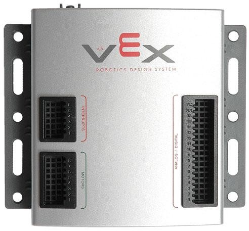
Then you say "Some docs say the signal should be the normal 0v to 5v." Do you have actual documentation for the Vex Controller? If I search for the VEX V.5 I find something totally different from what you have.
I can't find anything on VEX. (Well, what I find doesn't match what you [or I] have.)
Info from this week's video meeting.
====== 20250619 ROS Lawn Tractor Automation meeting - Length 20:58 This video: https://youtu.be/PXXC-sOjTpU
Chat/Notes: Al's Miro board: https://miro.com/app/board/uXjVM1yzdFo=/ Al's github: https://github.com/jones2126/ Al's Jupyter Notebook directory. https://github.com/jones2126/ros1_lawn_tractor_ws/tree/master/project_notes/jupyter_notebooks Al's gist channel: https://gist.github.com/jones2126
Index: 00:00 Jeff: Intro 00:20 Jeff: Talks about Bob's recent motor driver board. Suggestion to create a signal convertor for different boards. 03:05 Jeff: Holds up a board that has FwdPWM/RevPWM. Suggestion of microcontroller (like an Arduino) to convert signals. 04:00 Jeff: You could create an R/C test signal with an Arduino and a potentiometer. 04:10 Other ways to create the required R/C test signal. 08:10 Bob: Got his remote stop circuit working. Gives a demo. 10:15 Bob: Shows his web CAM displaying live video. The camera will be for AprilTags. 12:35 Bob: Has mysterious bright blobs on his video screen. We try to determine if they are from UFOs or ghosts or glare or a bad camera... 13:45 Jeff: Asks about Bob's stop circuit. 15:50 More discussion about the bright spots in the video. 19:20 Bob: Talks about upcoming life events.
==
Link to access the Slack channel: https://tractorautomation.slack.com/
Lawn Tractor Automation YouTube page: https://www.youtube.com/@lawntractorautomation2726/videos
Index for Lawn Tractor Automation Zoom meetings: http://sampson-jeff.com/RosAgriculture/LawnTractorMeetingNotes.htm http://sampson-jeff.com/RosAgriculture/LawnTractorMeetingNotes.txt
Index for the original ROS Agriculture Zoom meetings (~250 videos): http://sampson-jeff.com/RosAgriculture/readme.txt (Use following link, or newest file in that directory) http://sampson-jeff.com/RosAgriculture/ros-agriculture-youtube20230104.txt

I found one of my "Servo Testers". I can't post a direct link, since it has about 463 extra secret tracking characters. But if you go to Amazon and search for this you can see them: "RC+Servo+Tester+3CH+Digital+Multi+ECS+CCPM+Consistency+Speed" So I guess I have no excuse but to finish this project.
I will try to come up with the following modules for the next meeting: Arduino+Pot+Servo.h to generate servo pulses Oscilloscope plots of servo pulses Printouts of servo decode An output driver for PWM/Dir motor control Either output driver for FWDEn/REVEn, or logic circuit to convert from PWM/Dir
Status update on first steps to use IBT-2 motor controller with the goal of using it for steering control. Can talk more tomorrow.
Info from today's video meeting.
And we hit a milestone of 200 videos published.
====== 20250626 ROS Lawn Tractor Automation meeting - Length 38:35 This video: https://youtu.be/Zm5hz03G_tg
Chat/Notes: Al's Miro board: https://miro.com/app/board/uXjVM1yzdFo=/ Al's github: https://github.com/jones2126/ Al's Jupyter Notebook directory. https://github.com/jones2126/ros1_lawn_tractor_ws/tree/master/project_notes/jupyter_notebooks Al's gist channel: https://gist.github.com/jones2126
IBT-2 board. https://www.amazon.com/HiLetgo-BTS7960-Driver-Arduino-Current/dp/B00WSN98DC/ref=sr_1_5 Datasheet for BTS7960 driver chip. https://www.infineon.com/dgdl/BTS7960_Datasheet.pdf?folderId=db3a304412b407950112b408e8c90004&fileId=db3a304412b407950112b43945006d5d Bob's new board. https://www.amazon.com/DC5-12V-Dual-Channel-H-Bridge-Stepper-Controller/dp/B074TH1719/ref=sr_1_3 Cytron MD10C. https://www.amazon.com/Cytron-13A-Motor-Driver-MD10C/dp/B07CW3JZDH Cytron MD30C. https://www.amazon.com/Cytron-30A-Motor-Driver-MD30C/dp/B07L6HGFWY/ TimerOne() library. https://www.pjrc.com/teensy/td_libs_TimerOne.html Jeff's oscilloscope. https://www.amazon.com/Sds7102v-Channel-Oscilloscope-2-channel-Interface/dp/B00GP58T5C
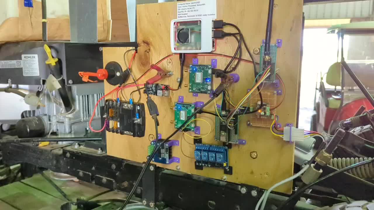
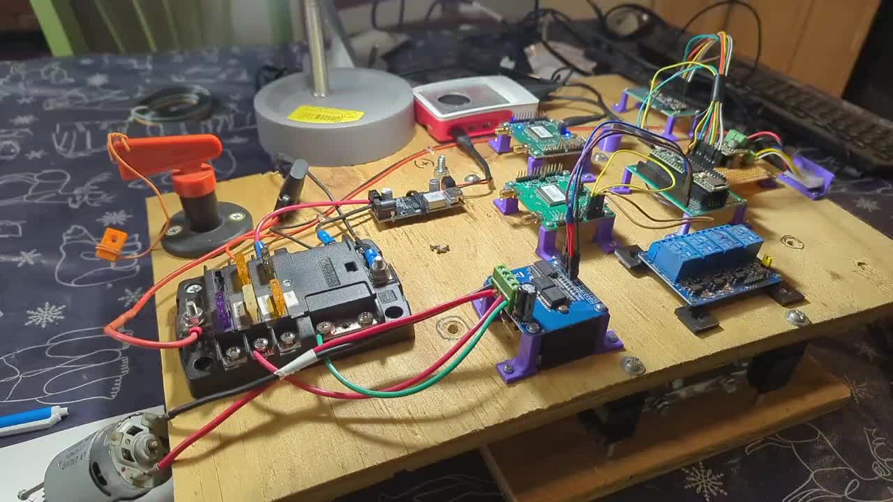
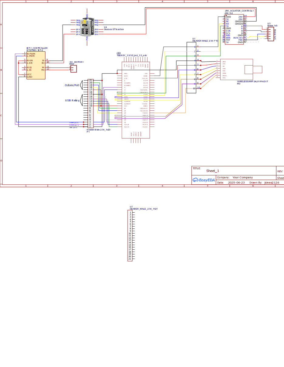
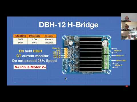
Index: 00:00 Jeff: Intro 00:50 Jeff: Talks about a motor controller conversion project. 01:20 Bob's new board. (DBH-12V on Amazon) 04:10 Jeff: Another board that Jeff and Al have. (IBT-2 on Amazon) 05:20 Jeff: Another board that Jeff has. (Cytron MD10C on Amazon) Another board that Jeff and AL have. (Cytron MD30C) 06:10 Jeff: More details on the IBT-2 driver board. 07:10 Jeff: Differences between Arduino AnalogWrite() and TimerOne() library. 07:25 Demo of power steering motor using AnalogWrite function. 10:05 We compare the AnalogWrite() to TimerOne() function. 16:20 Jeff: More details on the IBT-2 driver board. Thermal issues, bent pins, heatsink shorts. 18:50 The Cytron boards don't use heatsinks. More discussion of heat management on other boards. 21:05 Jeff: Shows his oscilloscope for possible documentation uses. 23:50 Jeff: Brief overall description of the motor driver convertor project. 26:00 Al: Makes comments on oscilloscope. 26:20 Al: Says his Cytron board also makes his motor squeal, but Jeff says any driver will squeal... 27:00 Al: Is always on a quest to get more resolution... 27:50 Al: Shows pictures of his hardware progress. Transmission control. 31:15 Al: Moves on to his steering control. 32:35 Jeff: The 5 volt connection. 34:00 A quick look at Al's code. And some diagrams. 37:25 Al: Next steps.
==
Link to access the Slack channel: https://tractorautomation.slack.com/
Lawn Tractor Automation YouTube page: https://www.youtube.com/@lawntractorautomation2726/videos
Index for Lawn Tractor Automation Zoom meetings: http://sampson-jeff.com/RosAgriculture/LawnTractorMeetingNotes.htm http://sampson-jeff.com/RosAgriculture/LawnTractorMeetingNotes.txt
Index for the original ROS Agriculture Zoom meetings (~250 videos): http://sampson-jeff.com/RosAgriculture/readme.txt (Use following link, or newest file in that directory) http://sampson-jeff.com/RosAgriculture/ros-agriculture-youtube20230104.txt
I’ve been about why my Sabertooth 2x12 failed. In my haste to do something I just connected the Vex signal wire to the Sabertooth. Things did work for a while before we did our final house move. The last couple of days I’ve been feeling some what better after surgery. So I’ve been researching the net for information.
I found several things I should have done but didn’t. First off I should have connect the grounds from the Vex to the Sabertooth. Vex documents say the motor ports are driven by 7.2 volts. A VOM measurement confirm the port supply is 6.8 v. The Sabertooth input requires 5v. The control signal is documented to be PWM. The Sabertooth requires R/C. To convert signals requires a low pass filter and possibly a level shifter. I’m still digesting the info I’ve found. Ive setup a notes file of the links and search questions. There is no organization to the notes so far. I just copy and paste as I go. Below is a copy of that notes file. I’m looking for a better way to share this info. Here goes,
bertooth Dual 12A 6V-24V R/C Regenerative Motor Driver - RobotShop
voltage for vex motors - Google Search
Difference between PWM signals. MC vs R/C - Let's Make Robots / Beginners - RobotShop Community
https://www.reddit.com/r/synthdiy/comments/ru2mmh/convertingpwmtoanalogvoltagewithoutthe_huge/
Arduino RC Circuit: PWM to Analog DC : 10 Steps - Instructables
https://www.instructables.com/Analog-Output-Convert-PWM-to-Voltage/
AI Mode All Videos Images Shopping Short videos Forums More
Tools
AI Overview
To use a PWM signal with a Sabertooth motor driver, you can either convert it to an analog voltage using an RC filter, or operate the Sabertooth in serial mode. In serial mode (dip switches 1 and 2 down), the Sabertooth accepts serial commands for controlling motor speed and direction. If using PWM, ensure it's within the Sabertooth's accepted range (e.g., 1-2 kHz for some models) and consider level-shifting if your microcontroller outputs 3.3V and the Sabertooth requires 5V.
Here's a more detailed breakdown:
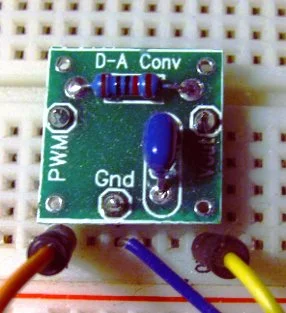
- Using a PWM to Analog Converter (RC Filter): • RC Filter: A simple RC filter (resistor and capacitor) can convert the PWM signal to a DC voltage proportional to the pulse width. • Components: A common setup involves a 10k ohm resistor and a 0.1uF capacitor. • Connection: Connect the PWM signal to the resistor, then the capacitor to the resistor and ground. The voltage across the capacitor will be the analog voltage for the Sabertooth. • Limitations: This method can be less precise and more prone to noise than serial mode.
- Using Serial Mode: • DIP Switch Configuration: Set DIP switches 1 and 2 on the Sabertooth to the down position for serial mode. • Serial Communication: The Sabertooth can be controlled via a microcontroller's serial output. Use a level shifter if your microcontroller outputs 3.3V and the Sabertooth needs 5V. • Commands: In serial mode, the Sabertooth accepts specific commands (often single-byte) to control motor speed and direction. • Advantages: Serial mode offers noiseless control, better failsafes, and a true zero command. Important Considerations: • Voltage Levels: . The Sabertooth typically requires a 5V control signal. If your microcontroller (like an Arduino) outputs 3.3V, you'll need a level shifter. • PWM Frequency: . If using PWM, ensure the frequency is within the Sabertooth's supported range (e.g., 1-2 kHz for some models). • Current Limiting: . Be mindful of the Sabertooth's current handling capabilities and use appropriately sized wires. • Wiring: . Carefully follow the wiring instructions in the Sabertooth's user manual. Example using an Arduino and Serial Mode:
- Set the Sabertooth to serial mode (DIP switches 1 and 2 down).
- Connect the Arduino's serial output (e.g., TX pin) to the Sabertooth's serial input.
- Use a level shifter if needed to convert the 3.3V Arduino output to 5V for the Sabertooth.
- Use the Arduino's Serial.write() function to send commands to the Sabertooth. This video demonstrates how to use PWM signals with a Sabertooth motor driver:
33s
Re: Using PWM with Sabertooth motor controller Mon May 13, 2019 10:33 pm Its really hard to debug software PWM's without being able to inspect the output waveform with an Oscilloscope.
Reading up on the Sabertooth 25x2, it can be driven several ways. Its not clear from your post what mode are you using. Are you using the PWM to generate an analogue signal, and the Sabertooth is in Analogue Input Mode, OR is the Sabertooth in Hobby servo RC mode, and you are trying to generate a RadioControl Servo pulse train?
Taking a punt I assume option 1. So in this configuration, converting a PWM to a proportional voltage, requires a filter (R/C network). The value therein are very specific to the base frequency of the PWM train. My bet is the R/C time constant is too fast and PWM pulses are getting through the R/C filter and driving the Sabertooth silly.
So, the Sabertooth needs a clean, ripple free, analogue control voltage. I would isolate the fault thus. Drive the Sabertooth input with a simple potentiometer, say 1k, as a voltage divider and using a multimeter ensure that the Sabertooth behaves properly. Then use the multimeter to determine the voltage swing of the PWM R/C output, with no Sabertooth connected. Using the DMM on the AC setting will show up any ripple. I would expect to see less than say 100mv ripple. But again you really need an oscilloscope to debug this.
Going in blind, I would increase the capacitor and resistor in the filter and see what the result is.
I trust you used the example R/C filter in the Sabertooth datasheet and are running the pulse clock well over 1Khz. The higher the clock, the smoother the signal will be with the appropriate R&C values.
https://www.dimensionengineering.com/datasheets/Sabertooth2x25.pdf
https://www.dimensionengineering.com/datasheets/Sabertooth2X50HVQ
will pwm signals harm rc channel? N
No, standard PWM signals used in RC (Radio Control) systems are designed to be compatible with RC servos and ESCs (Electronic Speed Controllers) and should not harm them when used correctly. However, there are some important considerations: RC PWM vs. Other PWM: • RC PWM signals are a specialized form of PWM, characterized by a fixed pulse period (typically 20ms or 50Hz) and a variable pulse width (ranging from 1ms to 2ms). This pulse width dictates the servo's position or the ESC's speed. • Other PWM signals, like those used in some motor drivers, may have different frequencies and duty cycles. Connecting these to an RC channel could cause issues. Potential Damage: • Connecting two outputs together (e.g., an Arduino pin directly to an RC receiver pin) can be dangerous and potentially damage the components due to conflicting high and low states. • If you are attempting to adapt a non-RC PWM signal to control an RC device, you will likely need additional hardware or a microcontroller to convert the signal to the correct RC PWM format. Attempting to connect incompatible PWM signals without conversion can lead to unpredictable behavior and potential damage. In summary, as long as you are using the standard RC PWM signal coming from your RC receiver, it will not harm your RC servo or ESC. However, if you are attempting to connect a different type of PWM signal to your RC channel, ensure it is properly converted or you risk damaging your equipment.
VEX 3-wire motors, like the Motor 393 when used with a VEX Motor Controller 29 (MC29), are controlled using PWM (Pulse Width Modulation). Here's how it works: • PWM Signal: The VEX microcontroller (like the VEX Cortex or VEX V5 Brain's 3-wire ports) generates a standard PWM signal. This signal determines the speed and direction of the motor. • Motor Controller 29: The MC29 takes the PWM signal from the microcontroller and converts it into a variable duty cycle PWM signal. This variable duty cycle PWM signal then drives the 2-Wire motor. Essentially, the microcontroller sends a PWM signal to the MC29, and the MC29 translates that into the power and direction commands for the motor. Note: The 3-wire motor itself doesn't directly process the RC signal. It relies on the MC29 to translate the microcontroller's PWM signal into motor control.
Vex forum,
Quazar Jump to post
I am driving vex motors not servos sorry if there was any confusion. The motors have 3 wires, (Black(GND), Orange(VCC), White(PWM)). I have connected the black wire and orange wire to a separate power supply a 9v battery to be exact. The white pwm wire is connected to a pwm port on my arduino where I can send out pwm 5v signals. This setup does not work and the motor driver is unresponsive with random jitters. You also need to connect the black wire of the motor to ground on the Arduino. So: White & Black from the Arduino to the motor, and Red & Black from the battery to the motor
But when it is connected
robofreak Mar 2009
I am driving vex motors not servos sorry if there was any confusion. The motors have 3 wires, (Black(GND), Orange(VCC), White(PWM)). I have connected the black wire and orange wire to a separate power supply a 9v battery to be exact. The white pwm wire is connected to a pwm port on my arduino where I can send out pwm 5v signals. This setup does not work and the motor driver is unresponsive with random jitters. But when it is connected to the vex micro controller it works just fine. I have been thinking and I came up with 2 possible explanations, one the motor driver expects a pwm signal voltage equal to that of the input voltage (VCC), or two the pwm signal does not have enough power to trigger the driver(unlikely though).
You also need to connect the black wire of the motor to ground on the Arduino. So: White & Black from the Arduino to the motor, and Red & Black from the battery to the motor
But when it is connected to the vex micro controller it works just fine. I have been thinking and I came up with 2 possible explanations, one the motor driver expects a pwm signal voltage equal to that of the input voltage (VCC), or two the pwm signal does not have enough power to trigger the driver(unlikely though). The VEX does not use the same voltage for signal and power, so I don’t think that’s it. The VEX sends the battery voltage (6V-9V) directly to the red wire on the motor ports. The white wire is driven by the PIC micro which is generating 5V logic signals. This is essentially what you are doing, so that should be OK. Cheers, • Vex PIC Microcontroller V0.5 to cim Via VictorSp??? - FIRST / General Forum - Chief Delphi
https://www.dimensionengineering.com/datasheets/Sabertooth2x12.pdf
VEX PIC System – Delmarva Robotics

These guys are so impressive. They seem to make stuff out of thin air.
https://youtu.be/5ZufOy4BHWw?si=vegiE-ZNhS5MAu0T&t=1432


Working on finishing up my pin assignments for the Teensy on my tractor. I need to solder and test my 4-relay board which I had to earlier figure out how to adjust the jumper and VCC to handle 3.3V from the Teensy. Can discuss on Thursday.


I wonder how one of these might be good enough for the hobbyist’s
https://products.bestreviews.com/best-oscilloscope-kits?cid=17571377514

Pic Microcontroller
I’ve been about why my Sabertooth 2x12 failed. In my haste to do something I just connected the Vex V0.5 signal wire to the Sabertooth. Things did work for a while before we did our final house move.
PIC Microcontroller V0.5 - VEX Robotics general description (aka sales flier) with front and back pictures of microcontroller
https://web.archive.org/web/20171027223843/https://www.vexrobotics.com/276-2170.html same as above from company website
The VEX V0.5 microcontroller, similar to the VEX Cortex it preceded, generates Pulse Width Modulation (PWM) signals primarily for controlling devices like motors or servos. Here's how it works: • PWM Output: The VEX V0.5 has dedicated PWM output pins. These pins can generate a series of pulses with a fixed frequency but a variable duty cycle (the width of the pulse). • Control: By varying the pulse width, you can control the speed and direction of connected devices. • Motor Control: For motor control, the VEX V0.5 sends the PWM signal to a motor controller WHICH IS BUILT INTO THE VEX V.05 MOTOR MODULE, which then regulates the power supplied to the motor. In essence, the VEX V0.5 microcontroller generates PWM by: 1. Setting the frequency: The PWM outputs have a fixed frequency, typically around 55Hz. 2. Varying the pulse width: The program on the microcontroller changes the duration of the "on" time (pulse width) within each cycle. 3. Controlling the device: The varying pulse width, when interpreted by a motor controller or servo, translates to different levels of power or position. Important Notes: • Period and Pulse Width: The PWM outputs have a period of 18ms, which corresponds to a frequency of about 55Hz, with a pulse width of 1-2 ms. • 3-Wire Ports: IN ADDITION TO THE VEX V0.5, the VEX V5 Brain, a successor to the VEX Cortex, can use its 3-wire ports as PWM outputs for controlling devices. • USER control: Selecting "USER control" on specific pins and using IFI_PWM will generate the same PWM signals that the Master would have generated.
Vex motors; https://www.google.com/search?q=voltage+for+vex+motors&ie=UTF-8&oe=UTF-8&hl=en-us&client=safari
AI Overview
In VEX robotics, both PWM (Pulse Width Modulation) and RC (Radio Control) systems are used for controlling motors, but they serve different purposes. PWM is a signal used to control the speed and direction of motors, often through a Motor Controller 29. NOT USED WITH THE VEX V 0.5. RC refers to the radio control system, which includes the transmitter and receiver, that sends signals to the robot. Essentially, PWM is a method for controlling motors, while RC is the communication system that provides the input for that control.
Here's a more detailed breakdown: PWM (Pulse Width Modulation):
• Function:
PWM is a technique used to control the average power delivered to a motor, effectively controlling its speed. • How it works: A PWM signal is a series of pulses where the width of each pulse (the "on" time) is varied. By changing the pulse width, you change the average voltage applied to the motor, thus controlling its speed.
• VEX Example:
In VEX, NOT THE VEX V.0.5, the Motor Controller 29 takes a PWM signal (typically from a microcontroller's 3-wire port) and uses it to drive a 2-wire motor.
• Another Example:
ESCs (Electronic Speed Controllers) used in RC also use PWM signals to control the speed of electric motors.
RC (Radio Control): • Function RC systems are used for wireless communication between a transmitter (held by the user) and a receiver (on the robot).
• How it works:
The transmitter sends signals that are received by the receiver, which then often translates those signals into control signals for various components, such as PWM signals for motors.
In essence: • You use PWM to control the motors on your robot.
• You use an RC system to send commands to your robot, which are then translated into PWM signals to control the motors.

In my understanding for Vex V 0.5 …”motor modules” have the motor controller in the motor module.
I found several things I should have done but didn’t. First off I should have connected the grounds from the Vex to the Sabertooth. Luckily I never connected voltage pin (7.2 volts) to the Sabertooth. Vex documents say the motor ports (3 wire) are driven by 7.2 volts. A VOM measurement confirm the port supply is 6.8 v. The Sabertooth input requires 5v. The control signal, from the Pic processor V 0.5, is documented to be typical 5 volt logic. The Sabertooth requires R/C. To convert signals requires a low pass filter and possibly a level shifter.
Given all of this so far…using PWM with typical 5v logic…with OUT a middle wire voltage, why did it work 2 years ago?
AI Overview
To use a PWM signal with a Sabertooth motor driver, you can either convert it to an analog voltage using an RC filter, or operate the Sabertooth in serial mode. In serial mode (dip switches 1 and 2 down), the Sabertooth accepts serial commands for controlling motor speed and direction. If using PWM, ensure it's within the Sabertooth's accepted range (e.g., 1-2 kHz for some models) and consider level-shifting if your microcontroller outputs 3.3V and the Sabertooth requires 5V.
Here's a more detailed breakdown: Using a PWM to Analog Converter (RC Filter):RC Filter: A simple RC filter (resistor and capacitor) can convert the PWM signal to a DC voltage proportional to the pulse width.Components: A common setup involves a 10k ohm resistor and a 0.1uF capacitor.Connection: Connect the PWM signal to the resistor, then the capacitor to the resistor and ground. The voltage across the capacitor will be the analog voltage for the Sabertooth.Limitations: This method can be less precise and more prone to noise than serial mode. Using Serial Mode:DIP Switch Configuration:Set DIP switches 1 and 2 on the Sabertooth to the down position for serial mode. Serial Communication:The Sabertooth can be controlled via a microcontroller's serial output. Use a level shifter if your microcontroller outputs 3.3V and the Sabertooth needs 5V. Commands:In serial mode, the Sabertooth accepts specific commands (often single-byte) to control motor speed and direction. Advantages:Serial mode offers noiseless control, better failsafes, and a true zero command. Important Considerations: Voltage Levels:. The Sabertooth typically requires a 5V control signal. If your microcontroller (like an Arduino) outputs 3.3V, you'll need a level shifter. PWM Frequency:. If using PWM, ensure the frequency is within the Sabertooth's supported range (e.g., 1-2 kHz for some models). Current Limiting:. Be mindful of the Sabertooth's current handling capabilities and use appropriately sized wires. Wiring:. Carefully follow the wiring instructions in the Sabertooth's user manual. Example using an Arduino and Serial Mode: Set the Sabertooth to serial mode (DIP switches 1 and 2 down). Connect the Arduino's serial output (e.g., TX pin) to the Sabertooth's serial input. Use a level shifter if needed to convert the 3.3V Arduino output to 5V for the Sabertooth. Use the Arduino's Serial.write() function to send commands to the Sabertooth. This video demonstrates how to use PWM signals with a Sabertooth motor driver:
33s
Re: Using PWM with Sabertooth motor controller Mon May 13, 2019 10:33 pm Its really hard to debug software PWM's without being able to inspect the output waveform with an Oscilloscope.
Reading up on the Sabertooth 25x2, it can be driven several ways. Its not clear from your post what mode are you using. Are you using the PWM to generate an analogue signal, and the Sabertooth is in Analogue Input Mode, OR is the Sabertooth in Hobby servo RC mode, and you are trying to generate a RadioControl Servo pulse train?
Taking a punt I assume option 1. So in this configuration, converting a PWM to a proportional voltage, requires a filter (R/C network). The value therein are very specific to the base frequency of the PWM train. My bet is the R/C time constant is too fast and PWM pulses are getting through the R/C filter and driving the Sabertooth silly.
So, the Sabertooth needs a clean, ripple free, analogue control voltage. I would isolate the fault thus. Drive the Sabertooth input with a simple potentiometer, say 1k, as a voltage divider and using a multimeter ensure that the Sabertooth behaves properly. Then use the multimeter to determine the voltage swing of the PWM R/C output, with no Sabertooth connected. Using the DMM on the AC setting will show up any ripple. I would expect to see less than say 100mv ripple. But again you really need an oscilloscope to debug this.
Going in blind, I would increase the capacitor and resistor in the filter and see what the result is.
I trust you used the example R/C filter in the Sabertooth datasheet and are running the pulse clock well over 1Khz. The higher the clock, the smoother the signal will be with the appropriate R&C values.
https://www.dimensionengineering.com/datasheets/Sabertooth2x25.pdf
https://www.dimensionengineering.com/datasheets/Sabertooth2X50HVQ
will pwm signals harm rc channel? N
No, standard PWM signals used in RC (Radio Control) systems are designed to be compatible with RC servos and ESCs (Electronic Speed Controllers) and should not harm them when used correctly. However, there are some important considerations: RC PWM vs. Other PWM: RC PWM signals are a specialized form of PWM, characterized by a fixed pulse period (typically 20ms or 50Hz) and a variable pulse width (ranging from 1ms to 2ms). This pulse width dictates the servo's position or the ESC's speed.Other PWM signals, like those used in some motor drivers, may have different frequencies and duty cycles. Connecting these to an RC channel could cause issues. Potential Damage: Connecting two outputs together (e.g., an Arduino pin directly to an RC receiver pin) can be dangerous and potentially damage the components due to conflicting high and low states.If you are attempting to adapt a non-RC PWM signal to control an RC device, you will likely need additional hardware or a microcontroller to convert the signal to the correct RC PWM format. Attempting to connect incompatible PWM signals without conversion can lead to unpredictable behavior and potential damage. In summary, as long as you are using the standard RC PWM signal coming from your RC receiver, it will not harm your RC servo or ESC. However, if you are attempting to connect a different type of PWM signal to your RC channel, ensure it is properly converted or you risk damaging your equipment.
VEX 3-wire motors, like the Motor 393 when used with a VEX Motor Controller 29 (MC29), are controlled using PWM (Pulse Width Modulation). Here's how it works: PWM Signal: The VEX microcontroller (like the VEX Cortex or VEX V5 Brain's 3-wire ports) generates a standard PWM signal. This signal determines the speed and direction of the motor.Motor Controller 29: The MC29 takes the PWM signal from the microcontroller and converts it into a variable duty cycle PWM signal. This variable duty cycle PWM signal then drives the 2-Wire motor. Essentially, the microcontroller sends a PWM signal to the MC29, and the MC29 translates that into the power and direction commands for the motor. Note: The 3-wire motor itself doesn't directly process the RC signal. It relies on the MC29 to translate the microcontroller's PWM signal into motor control.
Vex forum,
Quazar Jump to post
I am driving vex motors not servos sorry if there was any confusion.
The motors have 3 wires, (Black(GND), Orange(VCC), White(PWM)). I have connected the black wire and orange wire to a separate power supply a 9v battery to be exact. The white pwm wire is connected to a pwm port on my arduino where I can send out pwm 5v signals. This setup does not work and the motor driver is unresponsive with random jitters. You also need to connect the black wire of the motor to ground on the Arduino. So: White & Black from the Arduino to the motor, and Red & Black from the battery to the motor
But when it is connected
robofreak Mar 2009
I am driving vex motors not servos sorry if there was any confusion. The motors have 3 wires, (Black(GND), Orange(VCC), White(PWM)). I have connected the black wire and orange wire to a separate power supply a 9v battery to be exact. The white pwm wire is connected to a pwm port on my arduino where I can send out pwm 5v signals. This setup does not work and the motor driver is unresponsive with random jitters. But when it is connected to the vex micro controller it works just fine. I have been thinking and I came up with 2 possible explanations, one the motor driver expects a pwm signal voltage equal to that of the input voltage (VCC), or two the pwm signal does not have enough power to trigger the driver(unlikely though).
You also need to connect the black wire of the motor to ground on the Arduino. So: White & Black from the Arduino to the motor, and Red & Black from the battery to the motor
But when it is connected to the vex micro controller it works just fine. I have been thinking and I came up with 2 possible explanations, one the motor driver expects a pwm signal voltage equal to that of the input voltage (VCC), or two the pwm signal does not have enough power to trigger the driver(unlikely though). The VEX does not use the same voltage for signal and power, so I don’t think that’s it. The VEX sends the battery voltage (6V-9V) directly to the red wire on the motor ports. The white wire is driven by the PIC micro which is generating 5V logic signals. This is essentially what you are doing, so that should be OK. Cheers,
Vex PIC Microcontroller V0.5 to cim Via VictorSp??? - FIRST / General Forum - Chief Delphi
https://www.dimensionengineering.com/datasheets/Sabertooth2x12.pdf
VEX PIC System – Delmarva Robotics
Just for giggles I popped the hood. Yep 2 processors. Search on google AI found some info if I want to dig in and spend some time. I’d rather focus on Rpi applications.

Info from this week's video meeting.
====== 20250703 ROS Lawn Tractor Automation meeting - Length 1:30:36 This video: https://youtu.be/YY4i-4NIG7U
Chat/Notes: Al's Miro board: https://miro.com/app/board/uXjVM1yzdFo=/ Al's github: https://github.com/jones2126/ Al's Jupyter Notebook directory. https://github.com/jones2126/ros1_lawn_tractor_ws/tree/master/project_notes/jupyter_notebooks Al's gist channel: https://gist.github.com/jones2126
Bob's new board. https://www.amazon.com/DC5-12V-Dual-Channel-H-Bridge-Stepper-Controller/dp/B074TH1719/ref=sr_1_3 Dronebot video. https://www.youtube.com/watch?v=ygrsIqWOh3Y The result page Bob posted for cheap oscilloscopes. https://products.bestreviews.com/best-oscilloscope-kits?cid=17571377514 EEV Blog channel on YouTube. https://www.youtube.com/@EEVblog (watch the full intro video) EEV Blog oscilloscope tutorial playlist. https://www.youtube.com/playlist?list=PLvOlSehNtuHsCTtj-T_vkpTTbBXW4sB51 The guy with the Swiss accent. https://www.youtube.com/@AndreasSpiess https://www.youtube.com/@AndreasSpiess/search?query=oscilloscope Way to find random tutorial links. https://www.youtube.com/results?search_query=oscilloscope+tutorial Other: https://www.youtube.com/watch?v=puWXEqVQ4Yk ($125 scope)
Index: 00:00 Jeff: Intro/Links 00:55 Jeff: We start talking about Bob's new board. Quickly devolves into complaining about Amazon marketing practices. 04:40 DroneBot video about various motor driver boards. 08:08 Warning about PWM limit and voltage pins. 13:15 Digging into the IBT-2 board not having a 5-volt supply. 25:10 Be careful of shorting out boards. 28:25 A tour of a motor driver setup. 30:30 Jeff: Pros and cons of different techniques. 35:50 Jeff: Creating you own servo pulse. 38:20 Jeff: Decoding RC pulse and running a motor. 40:50 Jeff: Theories on building a cheap scope. 45:45 Jeff: Bob had asked about cheap oscilloscopes. 46:15 We click on each one to see the details. 58:30 We look for Jeff's scope for reference. 1:08:25 We look for a couple of references to tutorials, definitions, recommendations. 1:15:25 Topics next week? 1:16:00 Why your driver board may burn up (if over 98% PWM). 1:18:30 Difference between PWM and PWM...
==
Link to access the Slack channel: https://tractorautomation.slack.com/
Lawn Tractor Automation YouTube page: https://www.youtube.com/@lawntractorautomation2726/videos
Index for Lawn Tractor Automation Zoom meetings: http://sampson-jeff.com/RosAgriculture/LawnTractorMeetingNotes.htm http://sampson-jeff.com/RosAgriculture/LawnTractorMeetingNotes.txt
Index for the original ROS Agriculture Zoom meetings (~250 videos): http://sampson-jeff.com/RosAgriculture/readme.txt (Use following link, or newest file in that directory) http://sampson-jeff.com/RosAgriculture/ros-agriculture-youtube20230104.txt
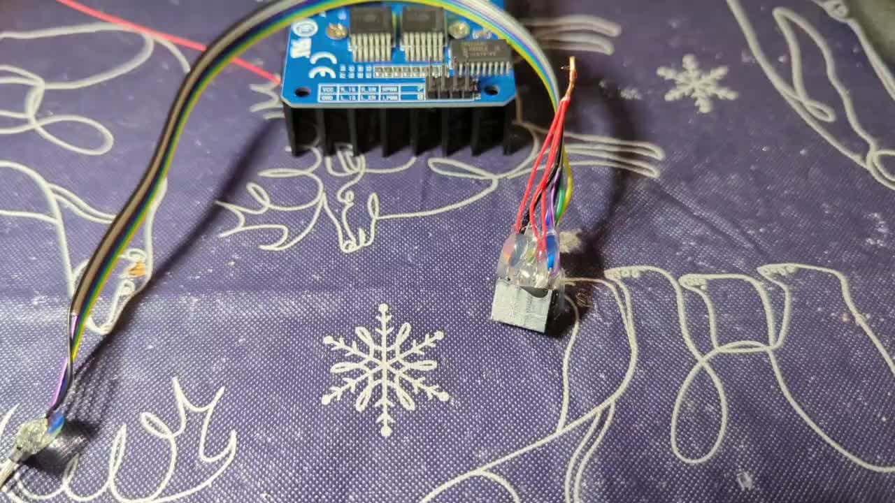
Working on a new wiring connector between my Teensy and IBT-2. I'll add hot glue after I add 5V to VCC and the enable pins.

Finally got the docs straighten out on Miro for my “stop circuit”
Here is the link , you may have to zoom in and out with - or +
https://miro.com/app/board/o9JkzvV0Pw=/?sharelink_id=59925973424
Test stand holding small (1.8mm diameter) pieces of wire to test my LJ18A3 induction proximity sensor.


I think my sheet metal guy could cut two 6" disks for me with 20 slots. That's what I'm thinking at the moment for my rear wheel odom.

Working toward desk testing so I can move to the field. Working on the shell of a function to control the steering motor including a PID. Here is the link: https://github.com/jones2126/tractor2025/blob/c424e5431b006fed754483f48807a1bcc3e52f6f/teensynrf24tractor20250624/src/main.cpp#L441
This still uses 'analogWrite(RPWM_Output, 0);', which whines. So I need to go back and find the notes from Jeff about the other library that does not whine.
I just got an email from ArduSimple. One of the topics was on ROS2 vs ArduPilot and GPS. After about 3 steps of deleting tracking info from the links I got to this: https://www.ardusimple.com/land-sea-or-air-robots-how-to-choose-the-platform-for-project-with-gps/
I decided to pack away all the Vex System stuff and just focus on the Rpi 5 and computer vision.
I found a couple of good you tube clips from Aleksander Habar. So now I’ve got some cv working with a usb camera on the Rpi 5 and Cheese. I’m half way thru the second video but I need to stop and get familiar with and load Visual Studio to finish Habar’s second video.
https://youtu.be/yGOWlflK3IM?si=ylu0Z_057dNSt8nH
https://youtu.be/Pm6JYAaLCPA?si=KNOOHVmQo4xnxikJ


Info from today's video meeting.
====== 20250710 ROS Lawn Tractor Automation meeting - Length 23:48 This video: https://youtu.be/hLh3vnhMw20
Chat/Notes: Al's Miro board: https://miro.com/app/board/uXjVM1yzdFo=/ Al's github: https://github.com/jones2126/ Al's Jupyter Notebook directory. https://github.com/jones2126/ros1_lawn_tractor_ws/tree/master/project_notes/jupyter_notebooks Al's gist channel: https://gist.github.com/jones2126
Video on IBT-2 current sensing https://www.youtube.com/watch?v=JaOuOL1J4-E Video on IBT-2 driver board testing (He has thermal tests on other boards) https://www.youtube.com/watch?v=Q7K8_nZU4mY Al's PWM code https://github.com/jones2126/tractor2025/blob/main/teensy35_IBT2_PWMtest/src/main.cpp Al's proximity test code https://github.com/jones2126/tractor2025/blob/main/teensy35_proximity_simple_test/src/main.cpp USB Type C PD Pigtail Cable - 18AWG https://www.amazon.com/XMSJSIY-Transmission-Extension-Charging-18AWG-1-2M/dp/B0C1YXM9PF Open CV tutorials https://youtu.be/yGOWlflK3IM?si=ylu0Z_057dNSt8nH https://youtu.be/Pm6JYAaLCPA?si=KNOOHVmQo4xnxikJ
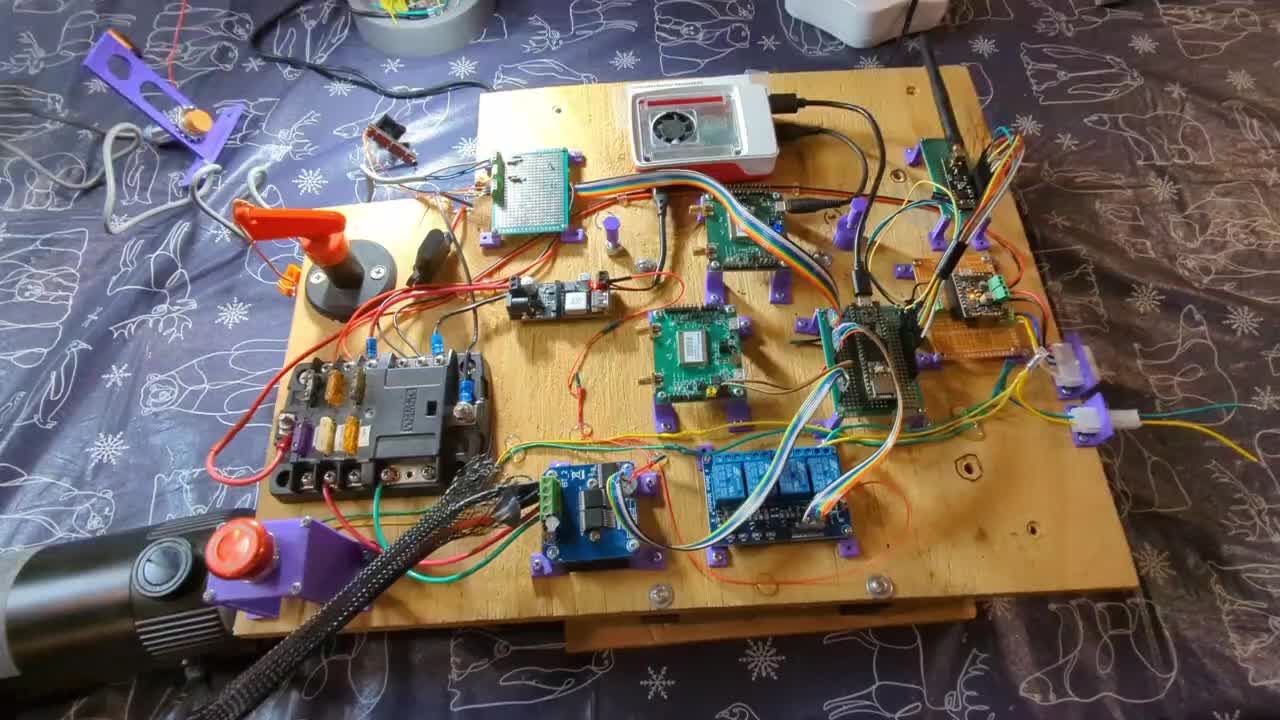
Index: 00:00 Jeff: Intro/Links 00:30 Jeff: Talks about cables and connectors. 02:40 Al: Shows the cables he was making. 04:00 Al: Shows his 3D printed encoder wheel. 05:00 Al: Shows a steel encoder wheel he is proposing. 08:25 A hub for an encoder wheel. 10:15 Maybe just bolt the encoder disk to the inside of the back wheels. 13:05 Al: Shows some code to read his inductive sensors. 14:40 Al: Talks about code to drive his motors. 16:30 Al: Gives a walk-through of his current control board. 18:10 Jeff: Makes comments about poking at live circuits with metal objects... 19:40 Bob: Talks about changes to his small robot. 20:10 Bob: Is looking at computer vision.
==
Link to access the Slack channel: https://tractorautomation.slack.com/
Lawn Tractor Automation YouTube page: https://www.youtube.com/@lawntractorautomation2726/videos
Index for Lawn Tractor Automation Zoom meetings: http://sampson-jeff.com/RosAgriculture/LawnTractorMeetingNotes.htm http://sampson-jeff.com/RosAgriculture/LawnTractorMeetingNotes.txt
Index for the original ROS Agriculture Zoom meetings (~250 videos): http://sampson-jeff.com/RosAgriculture/readme.txt (Use following link, or newest file in that directory) http://sampson-jeff.com/RosAgriculture/ros-agriculture-youtube20230104.txt
Interesting wheelchair, snowblower teardown and build to a robot....https://www.youtube.com/watch?v=3mXBYmciHS0&list=PLhKlFoJfD-H_mRdMZ4lvGFTW1e_c18p7v

Got the @Al Jones “Nomachine” software installed on the raspberry pi 5 robot, my iPad and my laptop. From iPad or laptop I can turn on cheese, which is on my raspberrypi robot. I can see the robot camera on the iPad and laptop. I was able to use the mirror function on the iPad to view the iPad screen on a Roku television. In other words, what ever my robot sees with its camera, I can see on the large screen TV in the living room. If I have the iPad or laptop in the living room, I can control the raspberry pi 5 on my robot from the comfort of my recliner. :-))
Screen capture off my iPad. The iPad can see everything on the raspberry pi five including camera..

I'm switching from Navspark GPS units to ArduSimple F9P's ($200 Basic version). Getting support from Navspark was simply too big of a pain. These are the results from the first 13 hours of testing my Base/Rover combination. After first achieving Fix, there have been 4 drops. The longest was 6.5 minutes, two drops at 3.5 minutes and one at 11 seconds. The Rover and Base were stationary the entire time. I will have to figure out how to live within this type of performance.
My Base pushes RTCM corrections at 1Hz to TCP socket port 6001 on my local network. Readme further explaining the setup (link) Test code on the robot/tractor to fetch the RTCM data and monitor status is here (link)

I’ve been banging my head trying to get Rpi5 GPIO going. DUH!…The Rpi5 doesn’t use the old GPIO library because it has new hardware and new software.
https://forums.raspberrypi.com/viewtopic.php?t=359742
When you reach a mountain top, what do you see?
Another mountain to climb!
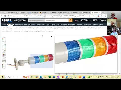
Just thinking. If I get this Andon https://www.amazon.com/LUBAN-Industrial-Rotatable-Flashing-Switchable/dp/B09X163JML?pdrdw=L3NI3&content-id=amzn1.sym.cd152278-debd-42b9-91b9-6f271389fda7&pfrdp=cd152278-debd-42b9-91b9-6f271389fda7&pfrdr=8G63BB932W7SR8Y4KRYG&pdrdwg=ZbfsJ&pdrdr=849bc527-77a3-4044-9255-0b76563c568a&pdrdi=B09X163JML&th=1|light I'm thinking blue to signify the tractor is in auto mode, red + buzzer if I lose RTK or some other significant error, yellow if battery is low or some other warning, green if the tractor is in manual mode. I would need to be able to switch 12 volts with a relay or some other device. Any other signals or higher priority items to use the lights for?


That looks like fun! In my robot I’d like to see different kinds of status; remote control thru Nomachine- using my iPad, laptop, or phone, low drive batteries, low Rpi voltage, maybe excessive current-wheels-servos. Was stop signal sent and indeed stop the bot. Hmm what else to go on a wish list?
Info from this week's video meeting.
I added links to ROS Agriculture videos for my flashing beacon and my LED status strip.
I also added an extra link for a video about controlling your house lights over the Internet.
====== 20250717 ROS Lawn Tractor Automation meeting - Length 1:03:47 This video: https://youtu.be/n0k-y3hCXdc
Chat/Notes: Al's Miro board: https://miro.com/app/board/uXjVM1yzdFo=/ Al's github: https://github.com/jones2126/ Al's Jupyter Notebook directory. https://github.com/jones2126/ros1_lawn_tractor_ws/tree/master/project_notes/jupyter_notebooks Al's gist channel: https://gist.github.com/jones2126
Al's github pages that are mentioned: https://github.com/jones2126/tractor2025/blob/main/BridgevilleRTKBase/README.md https://github.com/jones2126/tractor2025/blob/main/tractorRPi5/f9p_rtcm_client_071525.py https://github.com/jones2126/tractor2025/blob/main/BridgevilleRTKBase/rtcm_server_0714.py Flashing light column: https://www.amazon.com/LUBAN-Industrial-Rotatable-Flashing-Switchable/dp/B09X163JML Links to Jeff's beacon on ROS Agriculture. I found these on the ROS Agriculture index by searching for "beacon": 07022019 Community Meeting @4:406:20 https://www.youtube.com/watch?v=cf_l4b5_f6U 07122019 Lawn Tractor Meeting @7:0027:00 https://www.youtube.com/watch?v=kZkRv-ihn9o 07242019 Community Meeting @19:2542:35 https://www.youtube.com/watch?v=I1xGBc-KcXs 08022019 Lawn Tractor Meeting @9:1514:50 https://www.youtube.com/watch?v=JvzchYUuCJA LED status strip on ROS Agriculture. 10192018 Lawn Tractor Meeting @45:3049:10 https://www.youtube.com/watch?v=Sk8UloXSHSI 07262019 Lawn Tractor Meeting @39:0543:15 https://www.youtube.com/watch?v=b4GBtTtsa5g Actual demo 07302019 Community Meeting @42:35_46:30 https://www.youtube.com/watch?v=NAOeOLpYAuI Controlling lights over Internet. https://www.youtube.com/watch?v=NtAEMZTzFNU
Index: 00:00 Jeff: Intro/Links 00:30 Jeff: Talks about cables and connectors. 01:45 Jeff: Some comments about flashing beacons. 02:30 Jeff: Makes a second attempt at explaining why he doesn't have a wiring/jumper demo ready. Maybe an upcoming external video. 08:40 Al: Has new GPS receivers. Ardusimple uBlox F9P 13:05 Jeff: Says he is using the same uBlox boards. 14:50 Jeff: Points out that some of the links posted to Zoom chat are wrong. (We figured it out after we stopped recording...) 19:00 Al: Shows us some github documentation. And some code. 22:05 Jeff: Asks about reducing data that is being sent. 29:40 Al: Talks about a flashing light column. 32:50 Al: Next steps for his new GPS boards. 33:55 Jeff: Asks Al to show the picture of Jeff's beacon we made earlier. Jeff: Shows his beacon flashing. 42:05 Bob: Has "nomachine" running on his RPi5. 43:05 Bob: Talks about trying to drive R/C servos from RPi5. 45:00 Bob: Talks about remounting his RPi5 on a board. 47:00 Al: Says "nomachine" may not work as well as expected. 47:50 Bob: Says it might be possible to control RPi5 GPIO over the Internet. (See video in chat section.) 48:40 Bob: More about remounting his RPi5. 52:15 Jeff: Asks if Bob has any Arduino type boards lying around. (For alternative control.) 55:40 Drilling out the holes on a Raspberry Pi is revisited.
==
Link to access the Slack channel: https://tractorautomation.slack.com/
Lawn Tractor Automation YouTube page: https://www.youtube.com/@lawntractorautomation2726/videos
Index for Lawn Tractor Automation Zoom meetings: http://sampson-jeff.com/RosAgriculture/LawnTractorMeetingNotes.htm http://sampson-jeff.com/RosAgriculture/LawnTractorMeetingNotes.txt
Index for the original ROS Agriculture Zoom meetings (~250 videos): http://sampson-jeff.com/RosAgriculture/readme.txt (Use following link, or newest file in that directory) http://sampson-jeff.com/RosAgriculture/ros-agriculture-youtube20230104.txt
I tried resurrecting an old raspberry pi 1 B for low level control of servos or motors. It was frustrating to find an operating system that works well or even works. After some reading it’s possible I guess to program on Rpi5 and download to the Rpi 1 B. But, I did not want to spend the time trying to figure it out. So I went back to the raspberry pi 5. I’m slowly going through the documentation for GPIO zero and or demo some of the so-called recipes. The snippets of codes work, but I’ve got quite a bit of jitter on the camera, so I need to do more reading on how to reduce the jitter. Looks like I have to use PIGPIO pin factory..

View of the experimental breadboarding. Just controlling the “panning motion” for now. 5v Power for every thing is from wall worts. One supply was modified for the breadboard.

Arg!, yesterday the servo examples from the GPIO zero docs ran right away. I had a. Lot of jitter. So I used a heftier wall worts 2.5A. Did away with the bread board and wired the new supply to the servo. I also connected The pi grounds with the servo and new power supply. I saw improvement with the servo kind of. But now the example servo scripts don’t work. My understanding is GPIO.zero is just a wrapper for layers of Rpi.gpio and pigpio. The software should find the appropriate “pin factory”. I’m contacting forums for help.


Just posted to GitHub for help.
See : BobH91 GPIO zero documentation servo example #1205
I found an interesting video about servos. https://youtu.be/oeLmbXrHi_c?si=Quvjl8Hoo0P7DUkE It also talks about avoiding the usual servo jitters by using AdaFruits servo control board. I got the first part but when I tried to run the servo driver I ran into the same old error message, I’ve seen before. The one about running code in a python “environment”. So that’s my next mountain to climb. Reading everything I can about environments.
I’m beginning to understand why I get error messages Thonny, python and virtual environments. This is the link about what BookWorm can do:
https://www.raspberrypi.com/documentation/computers/os.html
Eventually I’d like to get back into Ubuntu after I am comfortable with BookWorm
This has been my misunderstanding all along. My most frequent error message: nstall Python libraries using pip
Bookworm changes to pip installation
In older versions of Raspberry Pi OS, you could install libraries directly into the system version of Python using pip. Since Raspberry Pi OS Bookworm, users cannot install libraries directly into the system version of Python.
Instead, install libraries into a virtual environment (venv). To install a library at the system level for all users, install it with apt.
Attempting to install a Python package system-wide outputs an error similar to the following:
pip install buildhat error: externally-managed-environment
× This environment is externally managed To install Python packages system-wide, try apt install python3-xyz, where xyz is the package you are trying to install.
If you wish to install a non-Debian-packaged Python package, create a virtual environment using python3 -m venv path/to/venv. Then use path/to/venv/bin/python and path/to/venv/bin/pip. Make sure you have python3-full installed.
For more information visit http://rptl.io/venv
note: If you believe this is a mistake, please contact your Python installation or OS distribution provider. You can override this, at the risk of breaking your Python installation or OS, by passing --break-system-packages. hint: See PEP 668 for the detailed specification. Python users have long dealt with conflicts between OS package managers like apt and Python-specific package management tools like pip. These conflicts include both Python-level API incompatibilities and conflicts over file ownership.
Starting in Raspberry Pi OS Bookworm, packages installed via pip must be installed into a Python virtual environment (venv). A virtual environment is a container where you can safely install third-party modules so they won’t interfere with your system Python.
Use pip with virtual environments
To use a virtual environment, create a container to store the environment. There are several ways you can do this depending on how you want to work with Python:
Finally! Some success, finishing the video and the commands in it. At one point I had an error message than I did not have lgpio. After more reading, it said install that package in the environment so I cleared out all the old stuff and typed in the commands from the video and it works!
@Bob Hassett I get that error as well. My suggestion:
$ sudo apt update $ apt search buildhat If 'buildhat' is available use: $ sudo apt install python3-buildhat
Well I think I have figured out my problem of getting data off my RS232 port of my solar charge controller. It was a wiring issue.
I previously looked at the female pinout of a DB9 connector, but should have been using the male pinout since I was hacking a USB to RS232 male connector. Now to see if I can get the PCB board version to work!
```from pymodbus.client.serial import ModbusSerialClient
client = ModbusSerialClient( port='/dev/ttyUSB0', baudrate=9600, stopbits=1, bytesize=8, parity='N', timeout=1 )
if client.connect(): print("Connected to Renogy controller.") result = client.readholdingregisters(address=0x100, count=35, slave=255) if result.isError(): print(f"Modbus error: {result}") else: registers = result.registers batterysoc = registers[0] batteryvoltage = registers[1] * 0.1 battery_charging_amps = registers[2] * 0.1 print(f"Battery Voltage: {batteryvoltage:.2f} V") print(f"Battery SOC: {batterysoc} %") print(f"Battery Charging Amps: {batterychargingamps:.2f} A") else: print("Failed to connect")```


This is the text that was discussed at our latest Zoom Meeting. I’ve added line numbers as a reference for discussion only.
file name: Text-Pan-Tilt
1 #text for a pan/tilt program on raspberry pi 5 using PCA 9586 servo driver. 2 #copy commands and paste the commands, exclude line numbers. 3 #I2C must be turned on 4 # transcribed from video…….. https://youtu.be/oeLmbXrHi_c 5 # @approximately 3 minutes 6 7 8 #start environment outside of project folder
9 #create an environment: 10 source pantilt/bin/activate 11 12#will see environment: 13#(pantilt)pi@raspberrypi 14 15 #install dependencies;
16 pip3 install Rpi5-lgpio 17 pip3 install adafruit-circuitpython-ServoKit 18 python 19 20 #will see python prompt in the environment: 21 >>>
22 #enter commands;
23 from adafruit_ servokit import ServoKit 24 kit=ServoKit(channels=16) 25 kit.servo[0].angle=90 26 kit.servo[0].angle=45 27 kit.servo[1].angle=10 28 kit.servo[1].angle=20
I just looked up the PCA9685. I don't see anything suggesting that you can run the two halves at different frequencies. I must have been crazy when I made that statement.
I was also surprised at the limited frequency range (24Hz-1526Hz). But it obviously works well for running R/C servos. And the blinking lights on my flashing beacon on my mini-tractor.
Info from this weeks video meeting.
====== 20250724 ROS Lawn Tractor Automation meeting - Length 1:01:53 This video: https://youtu.be/6QP7TEIMFMI
Chat/Notes: Al's Miro board: https://miro.com/app/board/uXjVM1yzdFo=/ Al's github: https://github.com/jones2126/ Al's Jupyter Notebook directory. https://github.com/jones2126/ros1_lawn_tractor_ws/tree/master/project_notes/jupyter_notebooks Al's gist channel: https://gist.github.com/jones2126
LED strip connectors https://www.amazon.com/dp/B0D17GZR9Q?ref=ppx_yo2ov_dt_b_fed_asin_title&th=1 LED clock without cutting LED strips https://www.youtube.com/watch?v=r_yobwaBWr0 Random examples of electronics paste/liquid flux Liquid flux https://www.amazon.com/Liquid-Dropper-Soldering-Electrical-Electronics/dp/B0CN29BZKV?s=hi Solder flux pen https://www.amazon.com/Solder-Liquid-Soldering-Electrical-Electronics/dp/B0CBT3KQDF?s=hi General search https://www.amazon.com/s?k=rosin+soldering+flux&i=tools Video Bob found for R/C servos on RPi. First half is running from GPIO. Second half uses Ada Fruit PWM board https://www.youtube.com/watch?v=oeLmbXrHi_c Another random video for Ada Fruit PWM board - He loads and configures the RPi 4 from scratch. https://www.youtube.com/watch?v=-x2EEIUMm6A
Index: 00:00 Jeff: Intro/Links 01:10 Jeff: Says he will stop committing, since he won't do it anyway. 01:35 Jeff: Found some robot parts, but hasn't done anything with them. 01:50 Al: Makes comments on Bob's "error: externally-managed-environment" Python issues. 04:30 Al: Is attempting to use solar power for his GPS base station. 05:55 Al: Is attempting to connect the RS232 port on his Renogy Charge Controller. 08:45 Al: Doesn't work... Begin debugging. 17:20 A discussion of pinout vs. of the diagram ensues. (The day I am looking at this. It looks like if you flip the board over then the order of pins is correct. So it looks to me like the hand drawn diagram from the github is wrong...) 22:55 Other configuration? 26:15 The Blue Tooth module for the Renogy controller. 28:40 Comments about oscilloscopes... 31:00 Al: Bought some connectors for LED strips. 32:50 Jeff: Has a story about mounting LED strips on edge so you don't have to cut them. And suggests getting a can of Rosin paste flux for soldering. 38:25 Jeff: Other videos on YouTube about basic electronics. 39:15 Bob: Is trying various methods to run R/C servos on a Raspberry Pi. 41:10 Bob: Python and environments. 49:25 Bob: Needs to safely save his code changes. 49:45 Bob: Next steps. 50:25 Jeff: (Incorrectly) states that you might be able to run each half of the PCA9685 at different frequencies. 51:25 Jeff: Makes comments about saving data. 54:55 Bob is going to post some code to our Slack channel. (Slack link is in description below video.) 55:20 Jeff and Al: discuss Slack channel backups. 57:30 Jeff: Talks about the RPi not doing exact timing for GPIO.
==
Link to access the Slack channel: https://tractorautomation.slack.com/
Lawn Tractor Automation YouTube page: https://www.youtube.com/@lawntractorautomation2726/videos
Index for Lawn Tractor Automation Zoom meetings: http://sampson-jeff.com/RosAgriculture/LawnTractorMeetingNotes.htm http://sampson-jeff.com/RosAgriculture/LawnTractorMeetingNotes.txt
Index for the original ROS Agriculture Zoom meetings (~250 videos): http://sampson-jeff.com/RosAgriculture/readme.txt (Use following link, or newest file in that directory) http://sampson-jeff.com/RosAgriculture/ros-agriculture-youtube20230104.txt
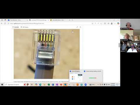
- I have my ESP32 connected to a TTL RS232
with RJ12 end connected to my Renogy solar controller using Modbus to
pull data off and passing to my RPi 3 for my Base Station. Took way
longer than it should have, but that's how it goes with me.
a. ESP32 script (link) b. RPi script that pulls the data 1/day using a cron job (link) - This is my script that runs on the RPi of the Base Station and pushes RTCM corrections (link)
- This is my initial test script that will run on the tractor, pull the RTCM data and push it to the two F9P GPSs to get to RTK Fix (link). This link will change after I clean up my repo because I'm getting a lot of test scripts building up.
- Readme files trying to maintain - overall (link); Base station setup (link) Can review tomorrow.
A couple videos I need to watch for Moving Baseline. The creator of the first video appears to be @JeffS
Two ArduSimple F9P receivers doing moving baseline with CORS correction
Getting the Heading of my Rover by using a moving base
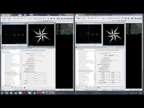
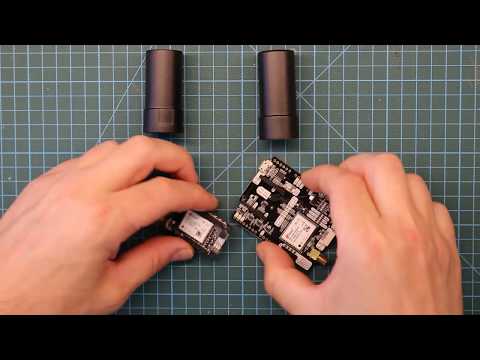
You might want to go here http://sampson-jeff.com/RosAgriculture/ros-agriculture-youtube20230104.txt
and do a search for baseline.
Info from this week's video meeting.
======
20250731 ROS Lawn Tractor Automation meeting - Length 47:30 This video: https://youtu.be/lM51OMaTl3A
Go to the HTML index to get the description for this meeting: http://sampson-jeff.com/RosAgriculture/LawnTractorMeetingNotes.htm#20250731
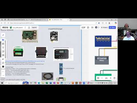
@JeffS I like the new way you are indexing. I think it will be quicker to find a topic of interest.
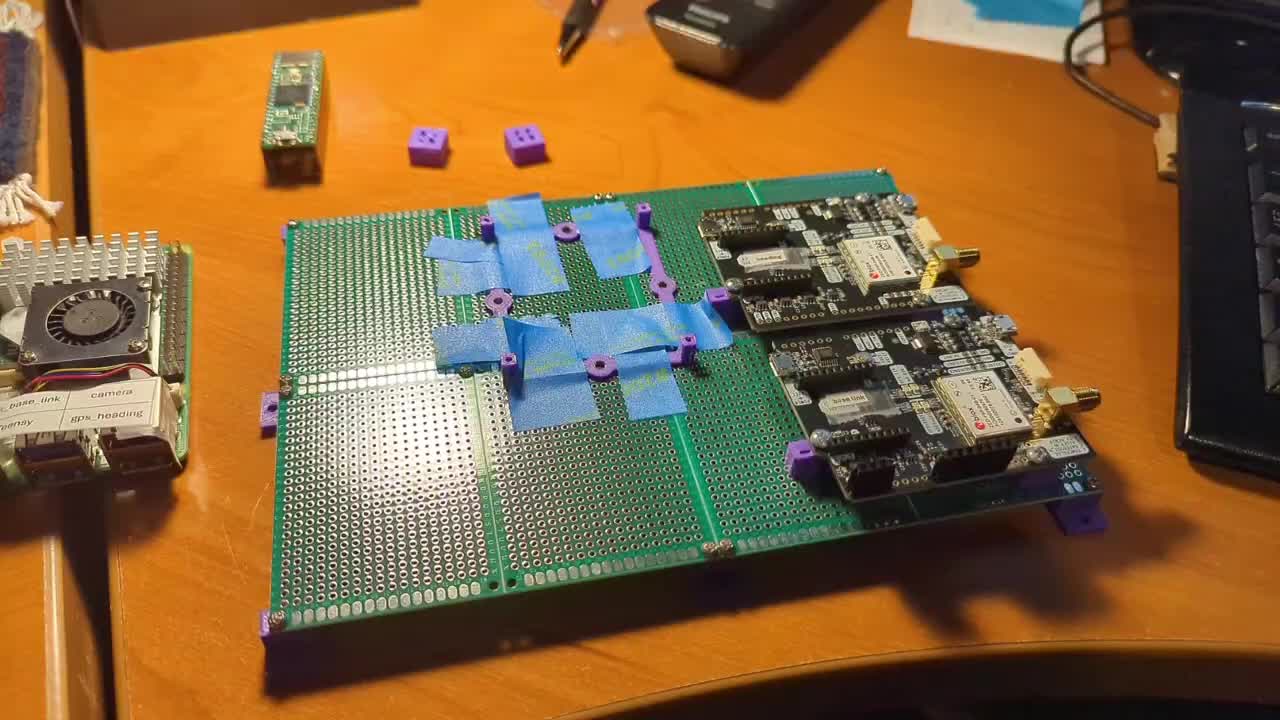


i’ve ordered two of these boards. I want to compare them against the Adafruit board that I’ve been using. The new boards have a capacitor mounted. The Adafruit board that I’m using now does not have a capacitor.

I’ve been playing around with GitHub’s Copilot to see if it can put together code. Attached are screenshots of my latest attempts.It seems you use keywords for it to come up with something. I have not had time to go thru this line by line yet.


Green light on the left shows my two nrf24's are talking. Which is good because I had to change SPI pins since I used my Teensy 4.1


My power was off for about 5 min. So it may/or may not allow me to attend meeting today...
Helpful spreadsheet if you need a spreadsheet format of pinouts for a Teensy 4.1, or 4.0


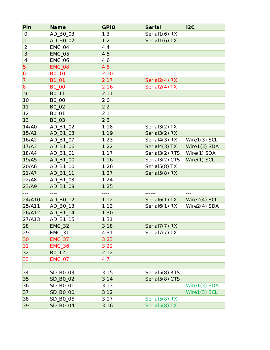
Here is a link to the tv I’m using as a monitor. When I can borrow it from the guest room 🤪 https://support.vizio.com/s/article/D40f-E1-Model-Information-1?language=en_US


I’m having difficulty trying to run this program in terminal. I don’t know what I’m doing wrong.
Btw I now have and using slack on my Rpi5. The white dots you see on the screen is the tv fault.u

*Thread Reply:* Instead of the .run I would try to change to the directory where textpantilt.py is located and then run the command python3 text_pan_tilt.py
You can run 'ls' to see what files are in the directory you are in.

*Thread Reply:* thanks @Al Jones, ithe program started to run but Ive got a syntax error. Ill work on that first. the problem has to do with sourcing the program for or in the environment. More later. thanks again about running programs/


I made some progress on getting heading from my second GPS. I have to update my instructions, because I switched from sending UBX messages to RTCM messages over UART1. I used a tape measure to confirm the 'Length' data is spot on also. One screen is from u-center. The other screenshot is from a test python script (link) to parse the heading and convert it to ROS ENU convention although its not in radians. When testing I moved the 'heading' antennae to 1.4 meters and the calculated heading error went down...interesting.
Next I need to get this running on my tractor RPi (i.e. not using u-center).


I was just reminded again how pathetic the original "configuration save" was in u-center for uBlox F9p. As @Al Jones has probably noticed, this is worthless: https://www.ardusimple.com/wp-content/uploads/2021/03/simpleRTK2B_FW113_HeadingKit_Rover_10Hz_Ardupilot.txt That is the format that ArduSimple is still using. From memory, there is an obscure page to save the configuration in the new readable format. I seem to recall it has the following characteristics:
- Save the data so it is human readable.
- Save only the configuration that has changed from default. So it might output a line like this:
UART1,BAUD,115200 But it has been about 2 years since I did any F9P configuration. About 5 years since I was playing with moving baseline or outputting configuration as decent readable format. So my memory is a little hazy. I'll spend time today and to recover that knowledge....
Ah hah!!! As much as I hate computers, sometimes they (computers/OS/browsers/search engines/archives) can be absolutely life-saving.
Six years ago (in a galaxy far, far away) a guy named jsampson asked a question on the uBlox blog/forum about readable configuration files. And mostly pointed out what works.
https://portal.u-blox.com/s/question/0D52p00008aAAYQCA4/converting-configuration-formats
The last reply said (paraphrasing) jsampson doesn't know what he is talking about, do this:
```TimAvular (Customer) 3 years ago
For people googling why it does not work like me:
In U-center 21.05, it turns out:
If you first go to View > Configuration View > CFG (Configuration) > Save current configuration > Send. I guess this is what jsampson means with "after the board is configured"

Then View > Generation 9 Configuration View > Advanced Configuration. Now the "Load differences from default" works, it lists all items to set, and then "Save to file..." also works and creates a human-readable ASCII config similar to what's available in GitHub
Hope that helps!``` So the second half of his post shows the page in u-center to use and mentions the check box...
And it only got 2 likes. So for 6 years people have continued using the old obscure method...
*Thread Reply:* Maybe we can discuss on Thursday. Yes I have noticed the save function and trying to make configuring easy is definitely not. Unfortunately, after I "Load differences from default" then "Save to file..." is still greyed out. Annoying, but I will write down my steps in a more old fashioned way.
Info from this week's video meeting. (Will we get the thumbnail this time??? No, it is still broken... No, its now fixed 8/10/2026!)
20250807 ROS Lawn Tractor Automation meeting - Length 1:26:47 This video: https://youtu.be/V5aAUrW5C3w
Go to the HTML index to get the description for this meeting: http://sampson-jeff.com/RosAgriculture/LawnTractorMeetingNotes.htm#20250807
======

I may have figured out why my last 3 weekly meetings will not display the YouTube thumbnail/preview in Slack. I'll do a couple more tests to see I can correct (my blunder)...
Finally got something to work. Uses a while loop, predefined angles and the input statement to continue. When I hit return it goes to the next given angle, In an endless loop.
What I learned…One has to be in an environment first, only then can one install dependencies from the terminal. After that Only then can launch a program from the terminal. #text of pan/tilt program from video WITH modifications
video time 3.08 https://www.youtube.com/watch?v=oeLmbXrHi_c
i2c must be on
At the top dir...ls to find project folder ...pan_tilt
then type:
source pan_tilt/bin/activate
will see (pan_tilt)pi@raspberrypi prompt
that means you are in the environment:(pan_tilt)pi@raspberrypi
install dependencies in the environment
pip3 install rpi-lgpio
pip3 install adafruit-circuitpython-servokit
to start program called textpantilt.py
type: python textpantilt.py
formal program;
from adafruit_servokit import ServoKit kit = ServoKit(channels=16)
Repeat a block of code until a condition is met
while count < 3:
Add other code you want to repeat here
kit.servo[0].angle=90

input("press return to continue")
print("execution resumed")

kit.servo[0].angle=45

input("press return to continue")
print("execution resumed")

kit.servo[1].angle=10

input("press return to continue")
print("execution resumed")

kit.servo[1].angle=50

input("press return to continue")
print("execution resumed")
count += 1
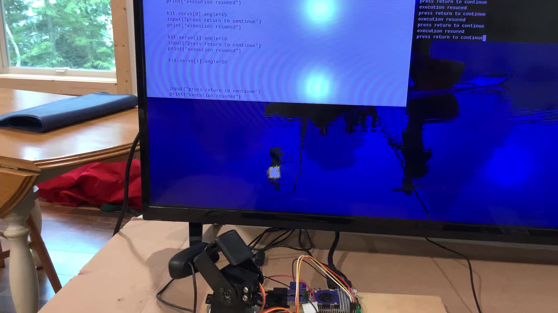
For a couple of years I noticed mowrs.com had been comandeering our YouTube meeting notifications. And creating fake reviews, I guess to get extra clicks?
https://www.mowrs.com/20250410-ros-lawn-tractor-meeting/
3 weeks ago I decided to try to block them by setting "Don't allow embedding" and "Don't allow remixing for shorts" when I uploaded the videos.
After a couple of weeks it looked like had successfully blocked mowrs.com. But it didn't occur to me that it may also be my Slack posting problem. Apparently it was. So I turned allow embedding back on. It doesn't fix the broken ones. Maybe the change just needs to propagate through their servers. And maybe those 3 will never work. I'm not going to worry about the broken ones. I'll just keep track if the new ones are working.
Here is a test of the "Allow embedding" turned on: https://youtu.be/qbnRlXTIZmI

Where was this thing when we were raising strawberries? It uses 24 robotic arms to pick strawberries. https://apple.news/ALdIPD0VQTciaFKYzVNlvpA
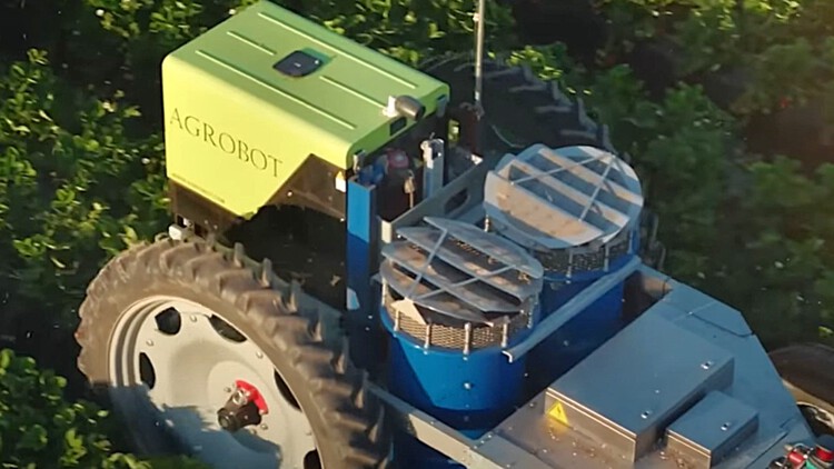
I think the mysterious missing YouTube thumbnail/previews is fixed. I just edited the last three bad messages and it added the thumbnail/previews back in. The first one I had to wait a day or two to catch up. The other two let me edit them immediately...
Cleaning up my F9P installation. I soldered my wires on the bottom side instead of using the DuPont connectors. 🙂


Starting to implement the two new servo boards that have capacitors. USB camera on pan and tilt servos works. I’m adding print statements so I know where the servos are going. The servos will need to be calibrated better. Temporary wiring to the motor driver from the second driver board is done . No code yet for the motor drivers. Hopefully I will control the camera position and the drive motors from a small Bluetooth keyboard.


https://learn.adafruit.com/python-virtual-environment-usage-on-raspberry-pi/overview https://learn.adafruit.com/python-virtual-environment-usage-on-raspberry-pi/basic-venv-usage https://learn.adafruit.com/python-virtual-environment-usage-on-raspberry-pi/more-venv-details
During zoom today I fumbled around trying to explain my use of python environments to implement 2 Servo driver boards. One board is for pan and tilt servos. The second board is drive a motor controller board MMD 20
Adafruit does a nice explaining things. I’m still learning.

[I was wrong. Its actually the second link that had multiple options. Just check them both...]
Here are a couple of options for large perf boards. (as usual, do some searching to get best price/quantity/shipping deal)
This first page has multiple options. One board is about 8"x12". https://www.amazon.com/Double-Sided-Universal-Packs-12x18/dp/B08WJBS4HK
https://www.amazon.com/Double-Sided-Universal-Packs-12x18/dp/B08WJDP144
Info from this week's video meeting.
20250814 ROS Lawn Tractor Automation meeting - Length 42:35 This video: https://youtu.be/h_4m3__CW2w
Go to the HTML index to get the description for this meeting: http://sampson-jeff.com/RosAgriculture/LawnTractorMeetingNotes.htm#20250814
======
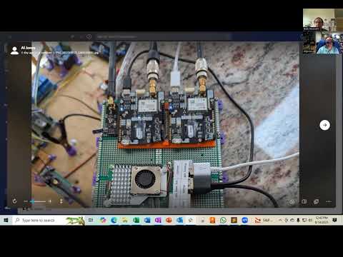
Sustainable agriculture https://www.youtube.com/watch?v=WfV8YxX_6N8

A video on magnetic shaft encoders. https://www.youtube.com/watch?v=byfn9hY5lS4
A video on basic debugging. https://www.youtube.com/watch?v=s5kzE0KEo1E


Info from this week's video meeting.
20250821 ROS Lawn Tractor Automation meeting - Length 43:02 This video: https://youtu.be/4bg-js-SvdI
Go to the HTML index to get the description for this meeting:
http://sampson-jeff.com/RosAgriculture/LawnTractorMeetingNotes.htm#20250821

Finally got NoMachine working on the Rpi5 as the server and as a client on my laptop. I can control the Rpi5 from my laptop. Trying NoMachine on my iPad is nothing but trouble at this point. I’ll need more time to figure out what is going on. Duh I keep forgetting I can only use one client (iPad or Laptop) at a time. So now I’m good with NoMachine.